04/2020 – 09/2021
Spend enough time around canards at Oshkosh or Rough River and you’re bound to hear about how bad the stock Cozy cowls are. The air flow simply doesn’t stay attached all the way to the trailing edge. I believed our cowls were likely even worse than stock due to the bump outs we had to create for intake pipe clearance. A simple oil flow test would allow us to confirm this. So way back in October of 2016 we flew up to Little Falls (about 20mi from St. Cloud) to conduct the test at a non-towered airport. Our good friend Rob is based there and stopped out to help us conduct the testing. With a quart of used oil and a paint brush, we taxied out to the hold short line, applied the oil near the leading edge of the cowl on both the top and bottom, and then quickly got in the air for a short 20 minute flight. Upon landing it was pretty easy to see there were a number of areas that were devoid of oil, indicating flow separation.
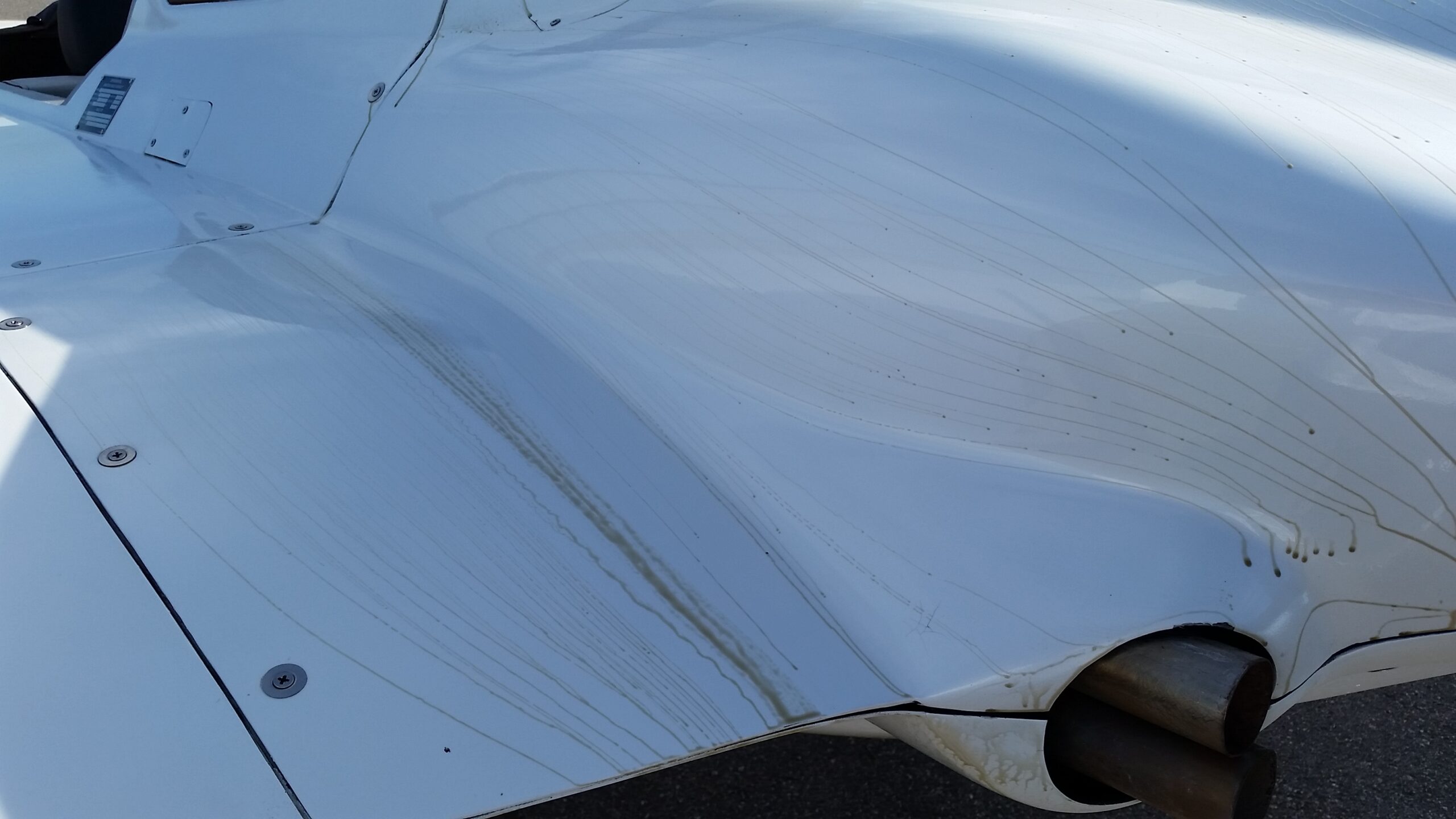

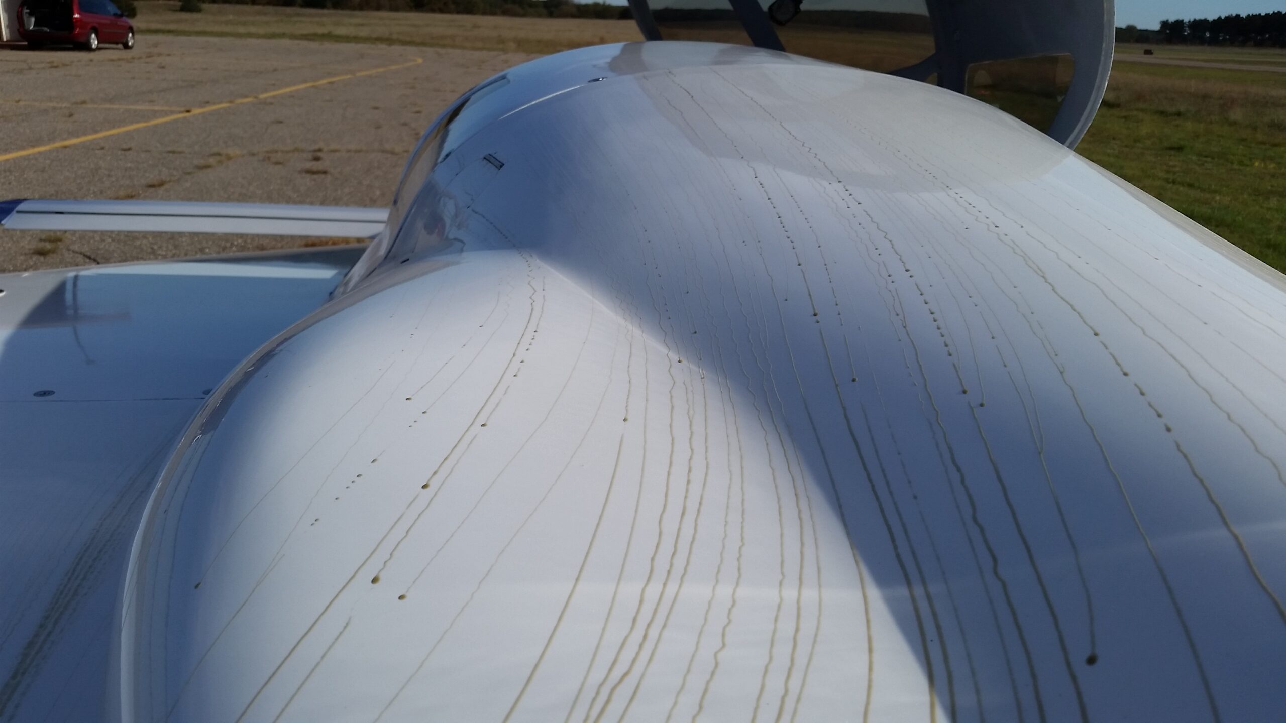
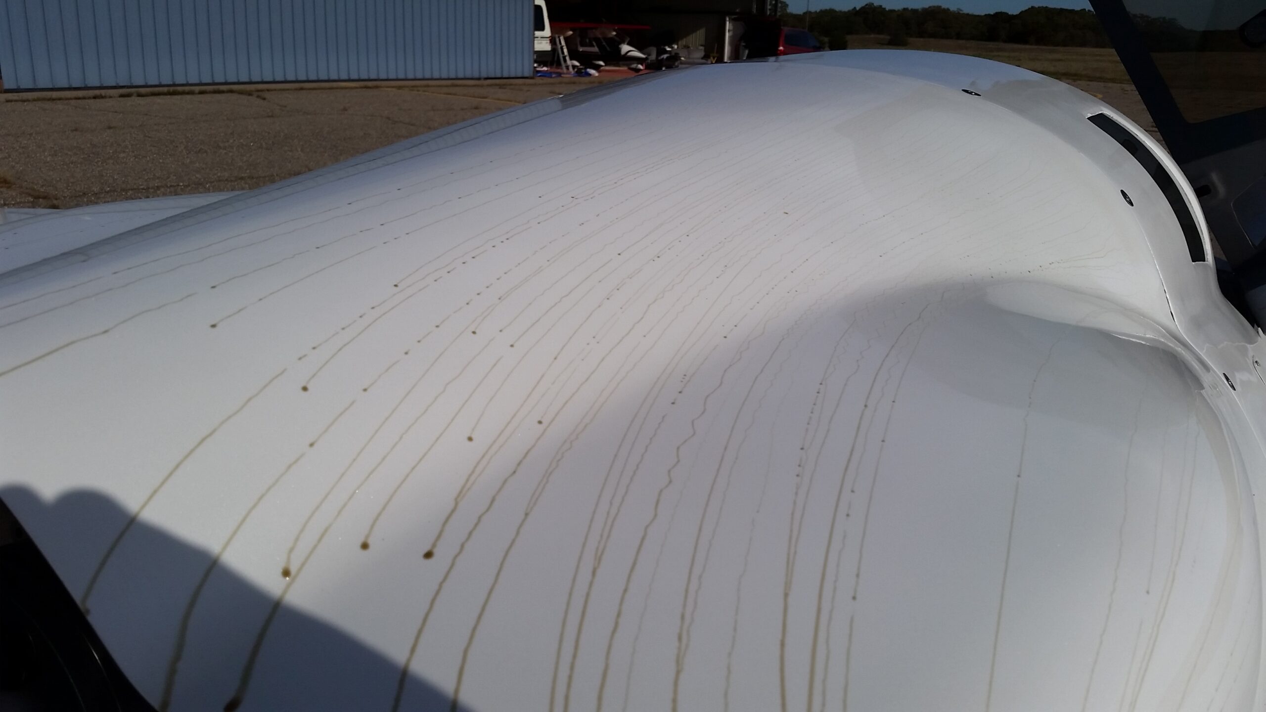


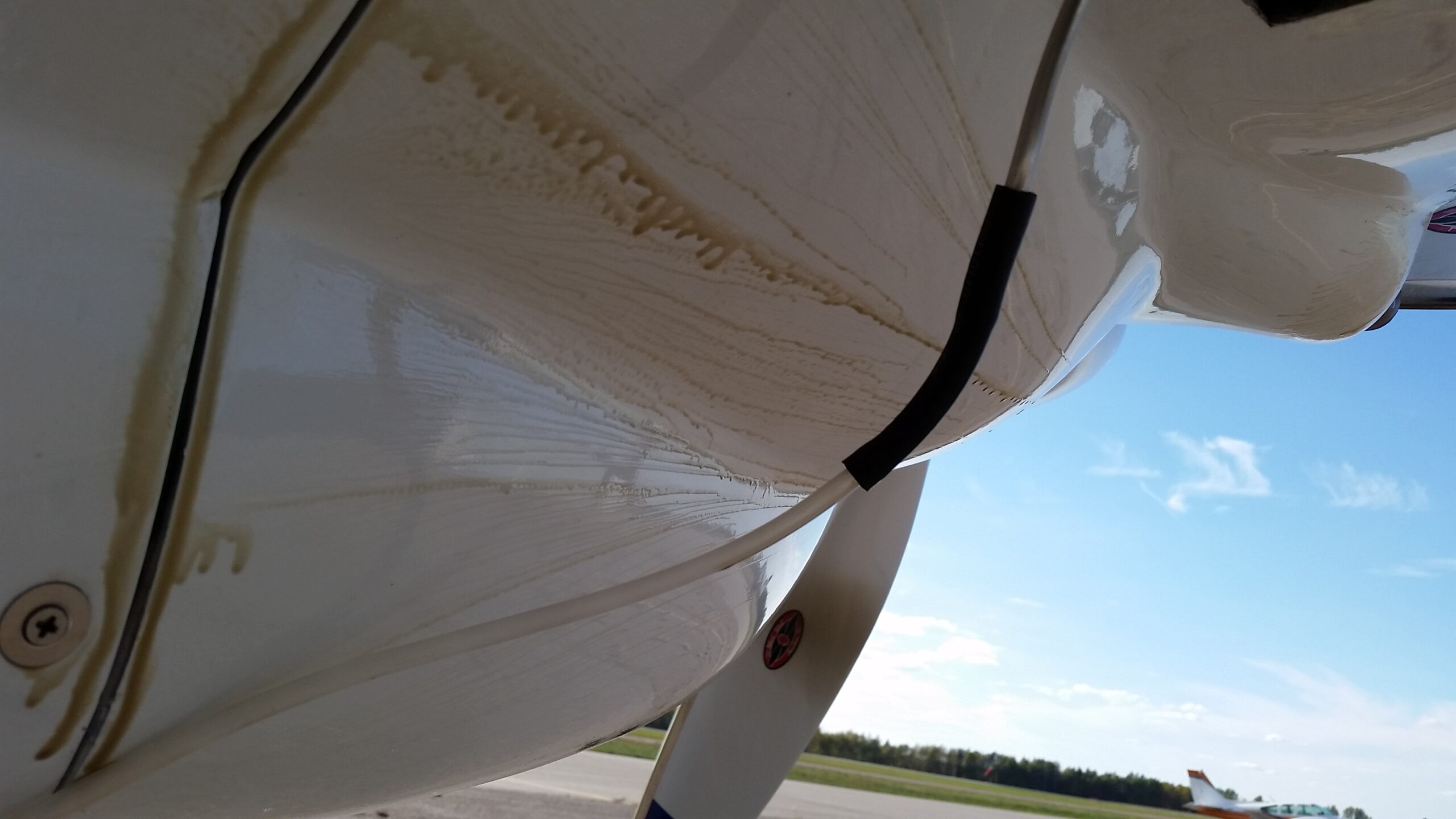

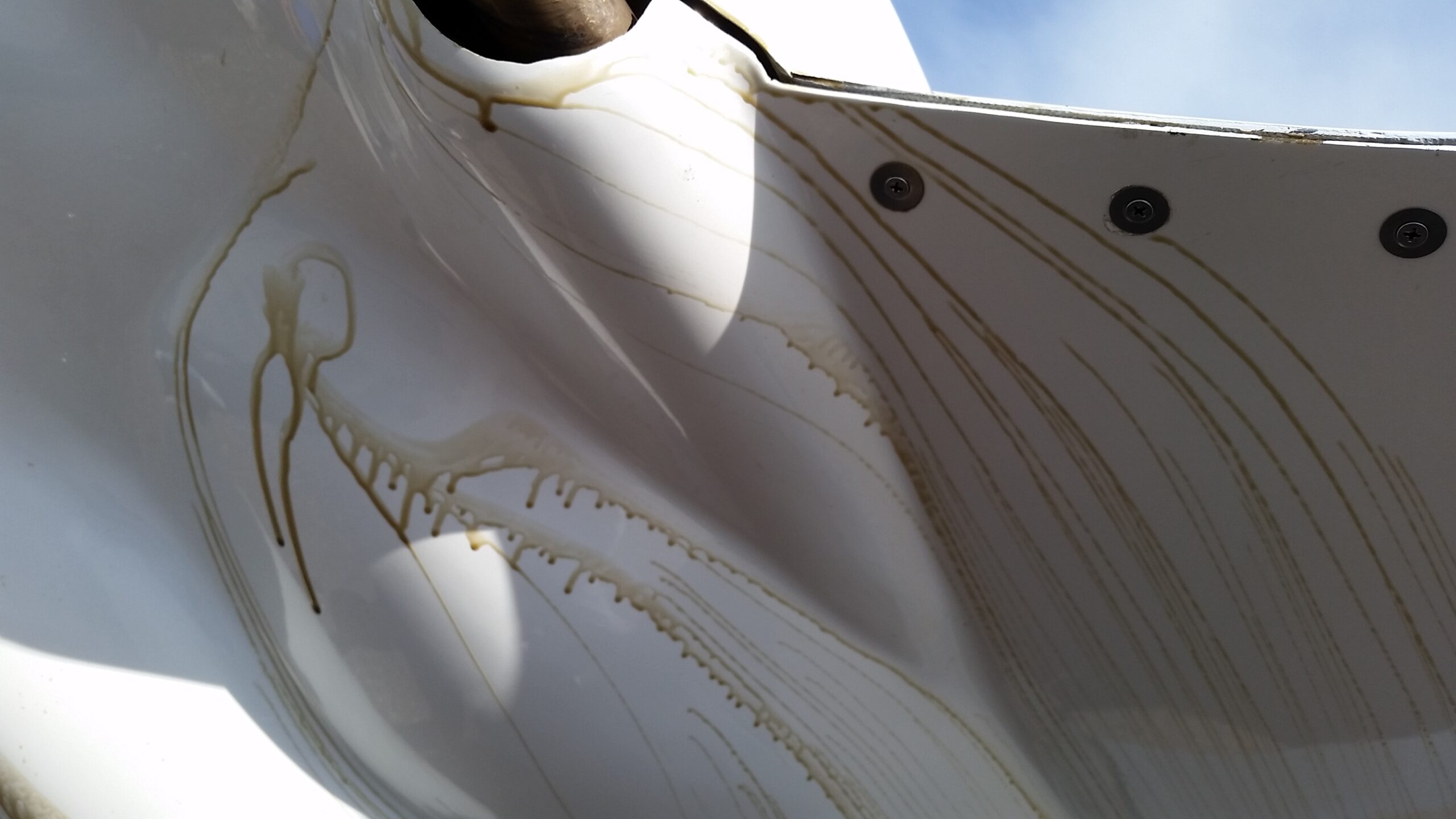


The top cowl wasn’t all that bad. The bottom cowl had separation at the areas we had added clearance for the intake tubes, as well as the areas where the stock cowl tapers in too quickly, thus leaving the airflow unable to follow. So with confirmation of the areas that needed to be addressed, the next step was to come up with a better design. Life, however, had other plans and would be over 3 years until we got back to solving this problem.
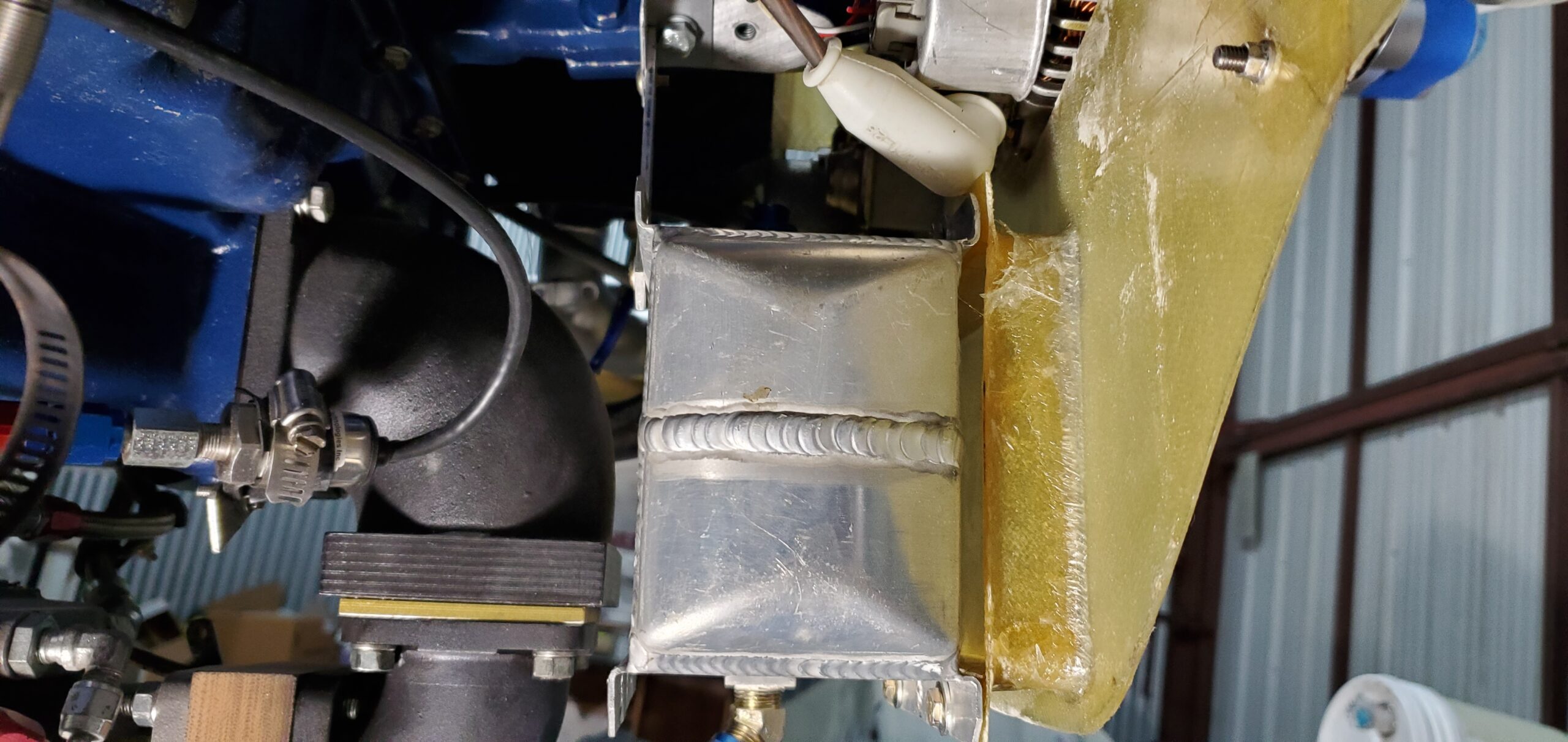
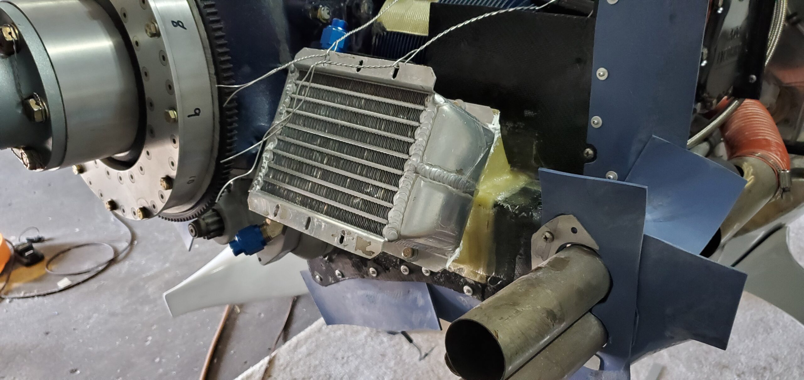
In April of 2020 I decided that since the pandemic was preventing me using the airplane for travel, now might be a good time to start in on designing better cowls. From the oil flow pics I knew the areas that needed attention, and one of those areas was the oil cooler exit. During the initial build I had heard so many horror stories of high oil temps, I opted for the largest oil cooler that was practical, a 17 row from Pacific Oil Coolers. While it did a great job keeping the oil temps down in even the hottest conditions, I knew that if I was going to clean up the cowl I would need to find a better location, and likely, a smaller cooler. What I didn’t want to do was change one problem for another and end up with an oil temp issues. In order to give myself the best chance at success I decided to take pressure measurements at various locations in the cowl to at least start with some data as guidance. To do this I placed piccolo tubes at various locations I thought might be suitable for the oil cooler and with the use of a couple dozen aquarium valves and lots of tubing I was able to measure pressure across various points under the cowl. The recently installed autopilot came in particularly handy for holding steady flight for the tests. A few years back during the oil flow study I had fitted the pressure transducer and measured the existing differential pressure across the oil cooler. This info along with the performance chart of the existing cooler gave me a rough idea of the heat rejection my current (well performing) setup provided and thus, a benchmark to start from. Using the pressure data I was gathering, along with the performance graphs of various coolers that would fit in the candidate locations, allowed me to narrow my focus for replacements. Ultimately I chose a 9 row, dual pass High Efficiency cooler from Pacific Oil Coolers. I had 3 possible location candidates; In front of the engine secured to the engine mount – with an exit duct leading to the forward baffle over the top of Cylinder #3, on the aft baffle behind cylinder #2, or on the forward side of aft baffle – in the bottom middle. I chose to first try the forward location with an exit duct over the top of the #3 cylinder.
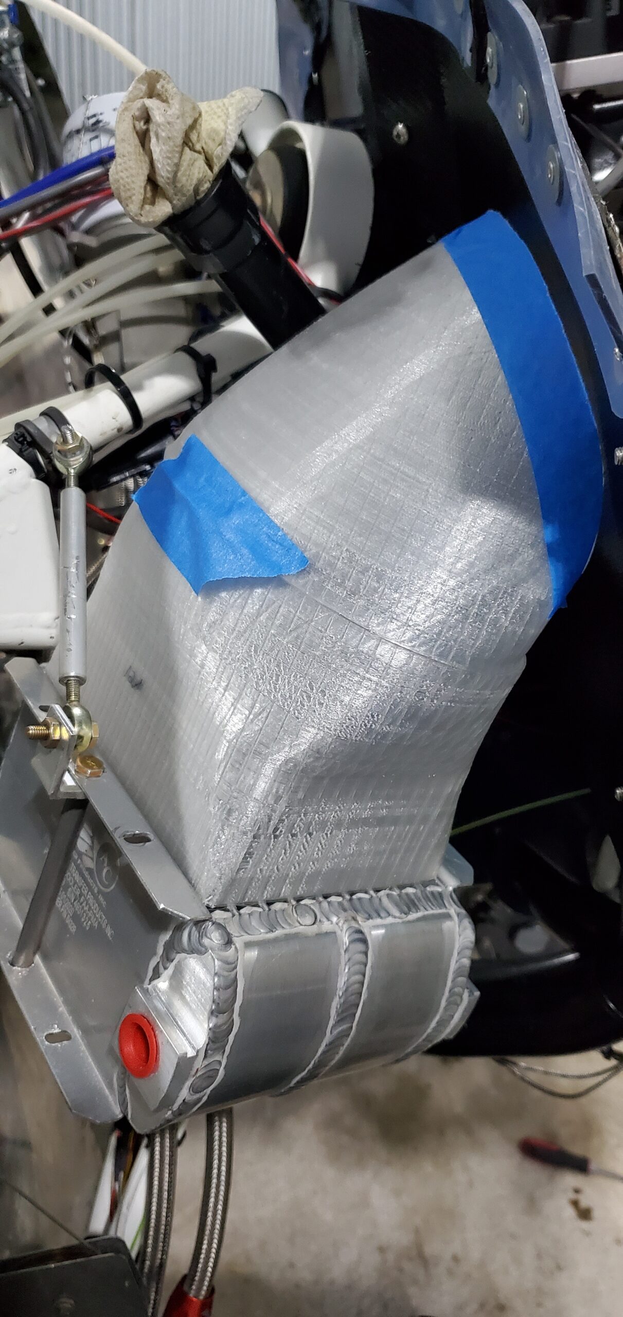
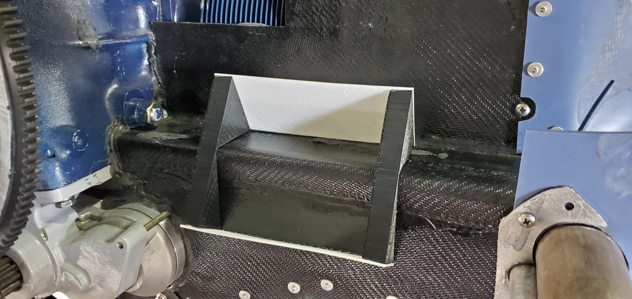
For the sake of brevity, I won’t dive into the all the details but sticking with the idea that I wanted to give the best chance of success, I decided to model the duct solution in SolidWorks, and use the built in CFD tool to test the design. This would allow me to see if the design was going to provide the differential pressure needed to adequately cool the oil. There is limited space under the cowls of a Cozy however and my designs were all coming up between “horrible” and “marginal at best”. I decided to try the marginal solution and see how marginal it really was. With the duct design modeled in SolidWorks, it was a simple matter of printing the duct on my 3D printer at about 2mm thick, applying a release tape, glassing over that with a few layers of BID fiberglass and allowing to cure. After cure, I used a heat gun to soften the printed duct and pulled it free from the glass. After installing the new oil cooler and duct solution, it was time to test fly it. The result of location #1??? Yup, marginal at best. Back to the drawing board to try my next selection, on the aft baffle behind cylinder #2.
While working on the next oil cooler solution, I was also working on how to solve the flow separation problem on the cowls. There has been a lot of work on this issue over the years by a number of the early canard builders. Gary Hertzler, Terry Schubert, and a number of others of all written articles in newsletters and online fora discussing the issue, and possible solutions. One of the added challenges I faced with 4TF is that the angle valve engine with its’ horizontal induction doesn’t fit very well under the stock cowls, requiring me to add ‘bump outs’ to clear the induction tubes. Those, combine with the stock cowls higher than optimal closure angle created a challenge for keeping flow attached. There wasn’t an easy way for me to model all this in the computer as precise dimensions would be difficult without high end 3D scanning hardware, so I approached this problem the old fashion way….trial and error with foam and fiberglass.
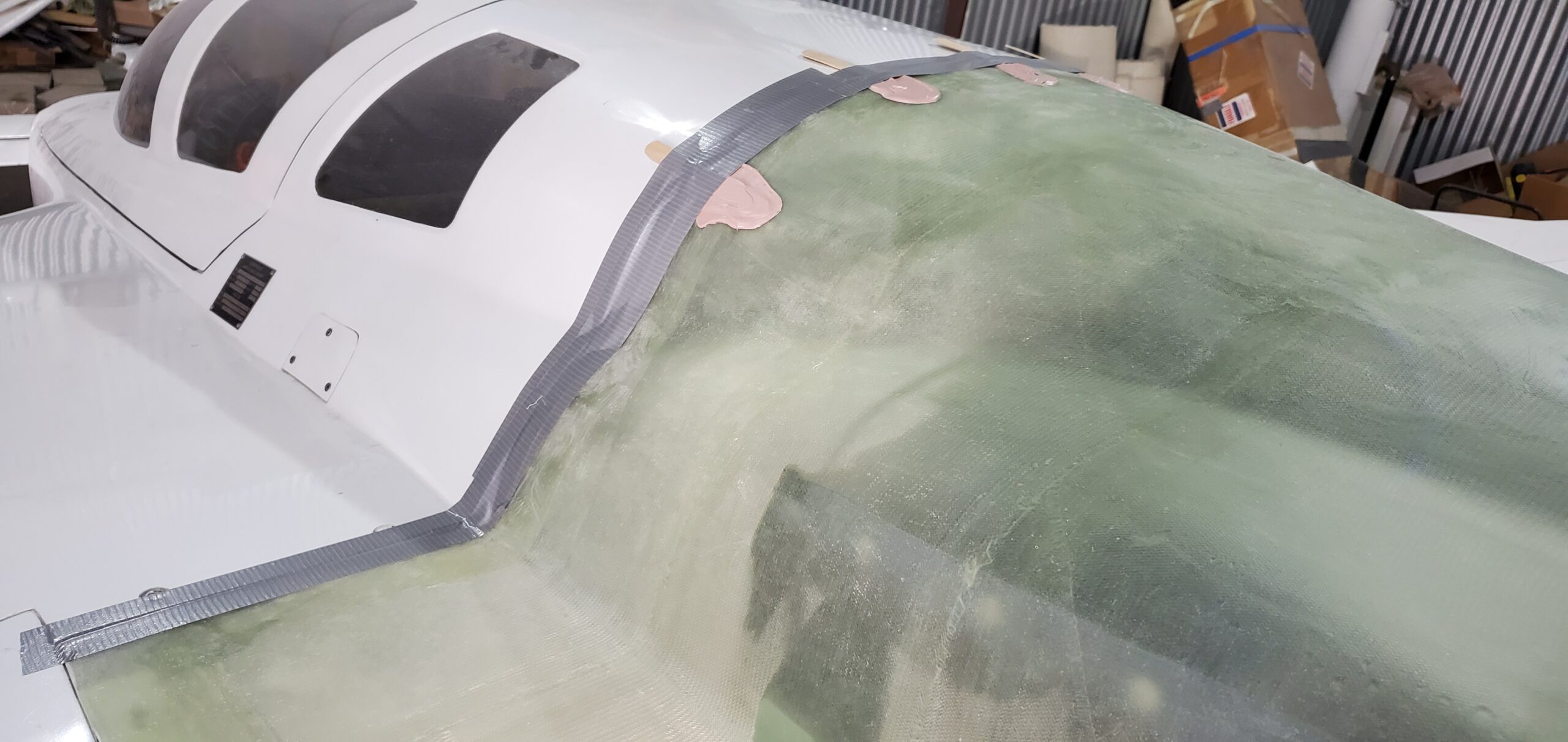
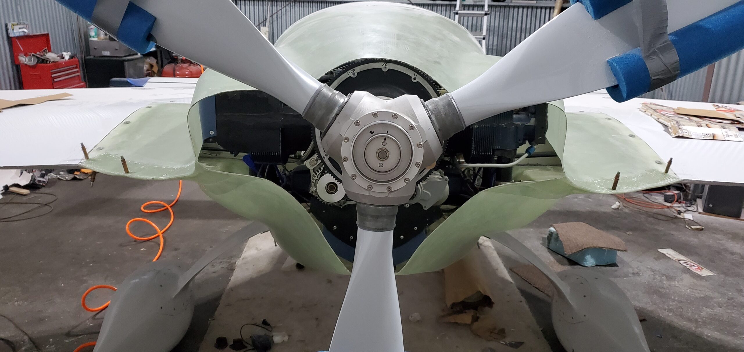
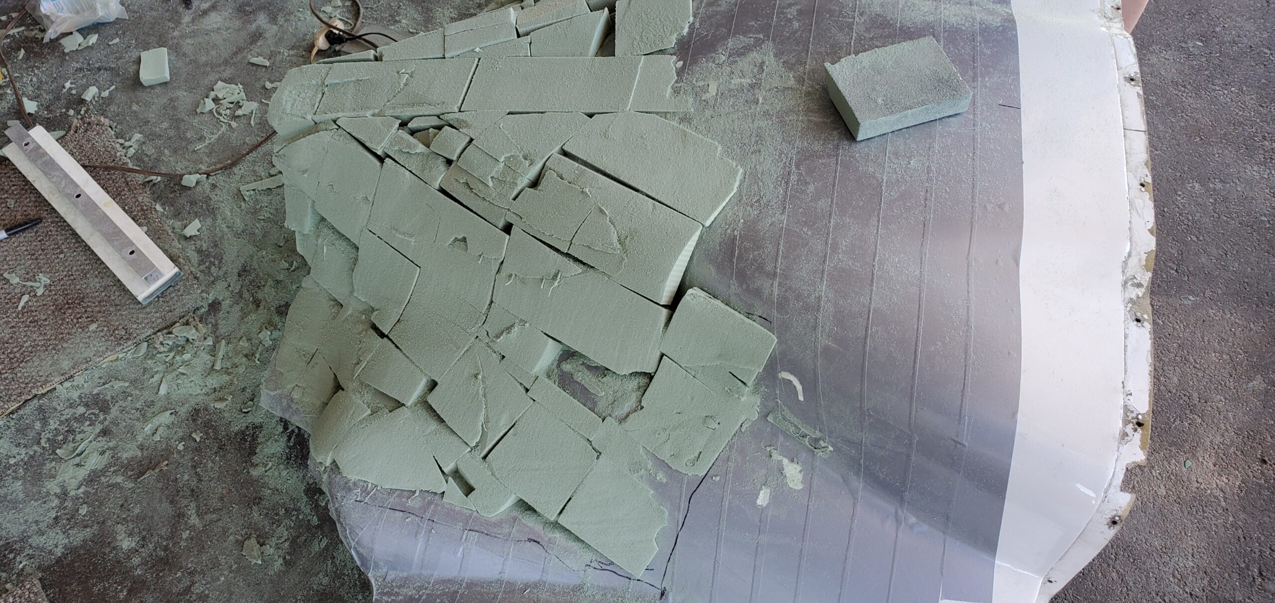
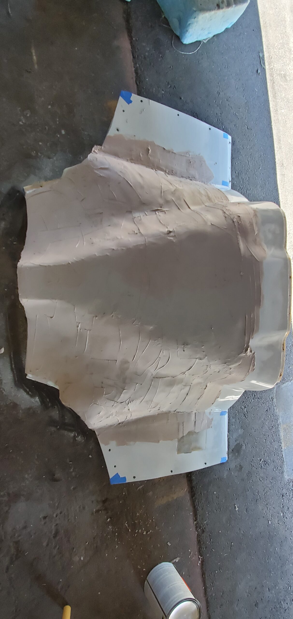
I decided to reshape the existing cowls with prosthetics for the purpose of testing the airflow solution. This would allow me to continue flying the plane (albeit with ugly, ‘in construction’ looking cowls) for the purposes of testing the second oil cooler location as well. Once happy with the cowl shape I would then use the old, modified cowls as plugs for making molds from which I could create new perfectly shaped cowls. Easy? Right? 🙂
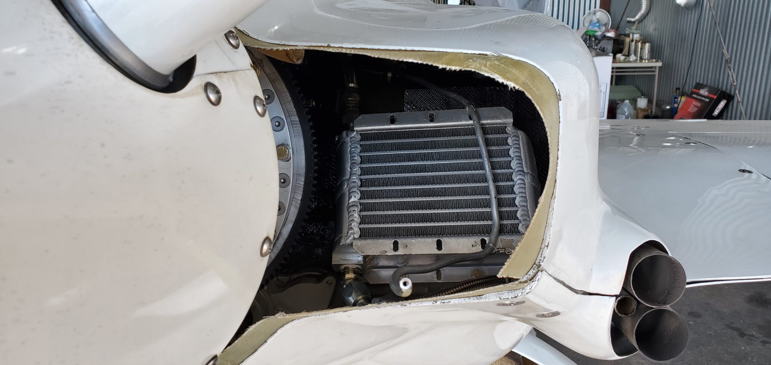
The first step was the hardest, sanding my nice, shiny, sparkly cowls where I would be attaching foam to build out the areas where the closure angle was too high. I just had to remind myself it was for the betterment of the plane. So while adding and shaping foam, cutting out bump outs, etc… I was also working to mount the oil cooler on the aft baffle behind cylinder #2. That location was better than the first, and was sufficient for flying in the northern Midwest where we rarely see temps over 95F, but I knew from trips I had made to southern states that I would need to do better. For now it would work, and I focused on getting the cowls completed.
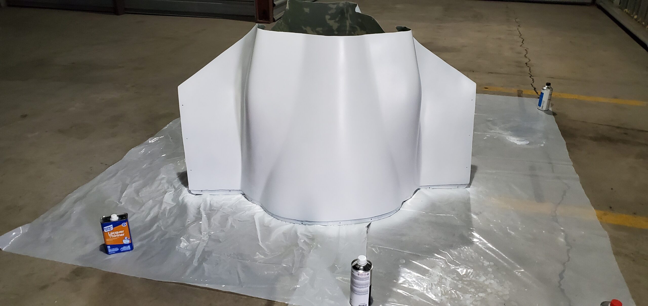
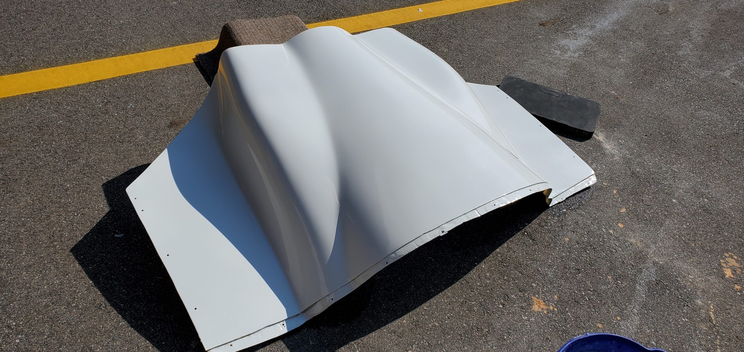
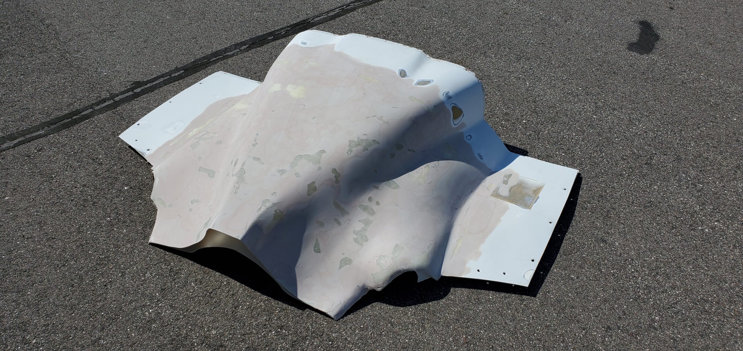
Once the cowl prosthetic shaping was complete it was time fill, sand and paint them so the finish was at least roughly comparable (albeit not the exact color) as the originals. With that complete I could reconduct the oil flow test for comparison to the original design. The results were great. The air was now staying attached all the way to the trailing edge. The exhaust bumps were still disrupting flow a bit though, so I decided I would opt for a new exhaust system that exited within the cowl exit instead of outboard of it. A little more work would be needed before I could make the molds.


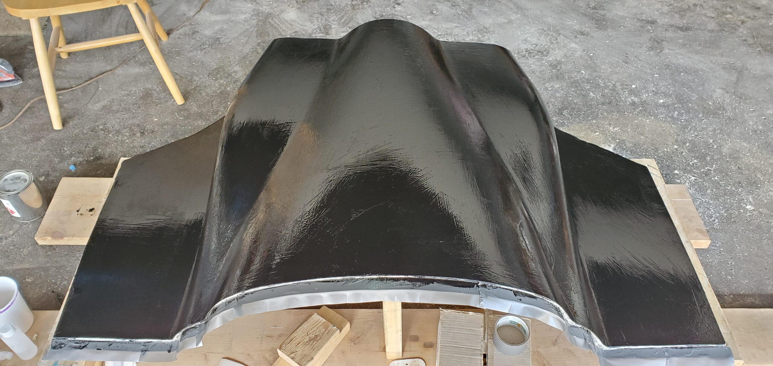
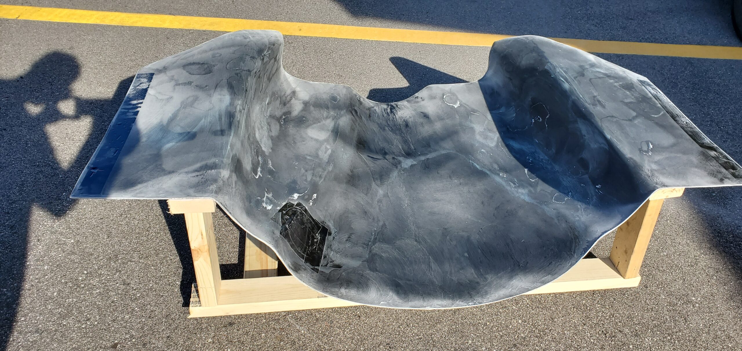
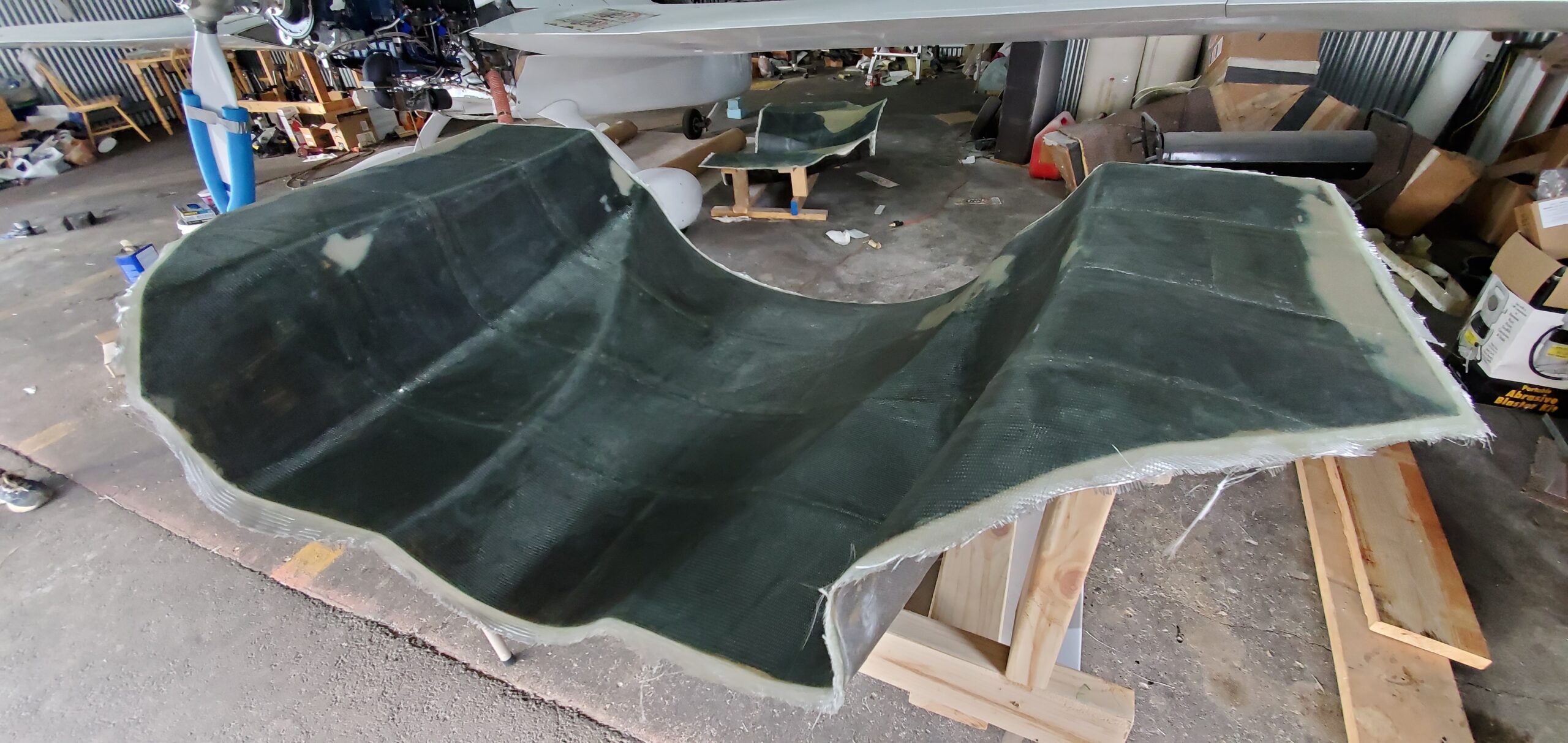
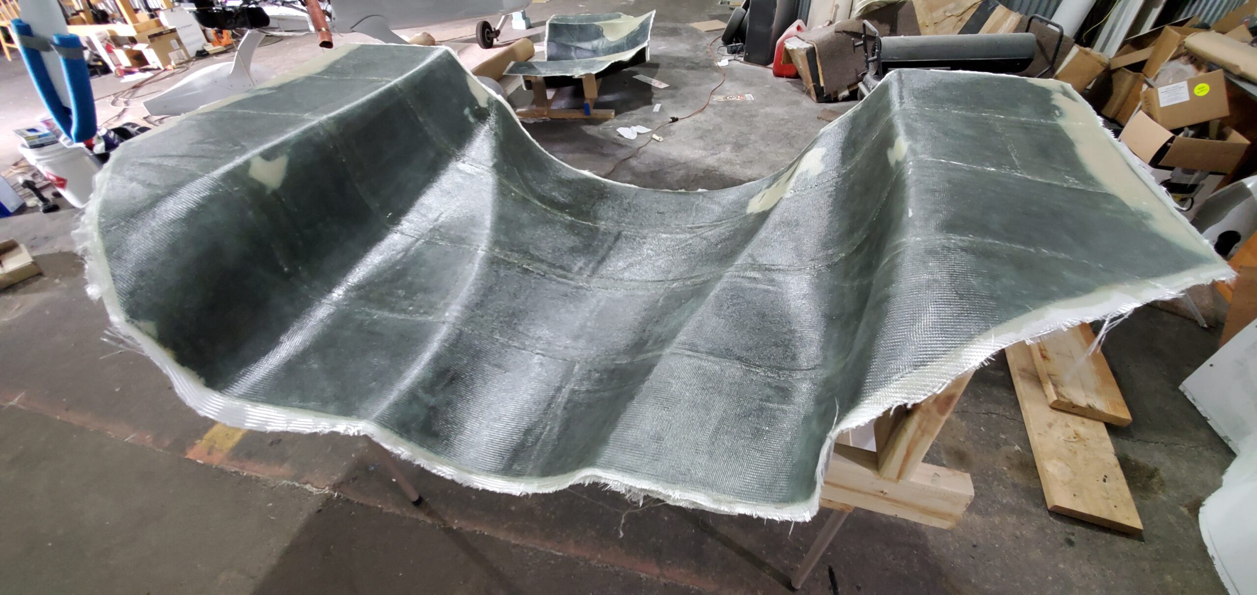
After a bit more prosthetic work with both the top and bottom cowl to eliminate the exhaust bumps, it was now time to make molds. This was the first time I had made molds before, so after getting some advice from others, I settled on the following process. First, ensure the finish is good on the part you’re pulling the mold from. Imperfections in this surface will be directly implanted in your mold, and subsequently your finished part. Second apply a good tooling gelcoat to the part. Third apply the appropriate number of layers of chopped glass mat, wetted out with polyester resin. I chose to use 3 layers of 1/8″ thick mat. Lastly, 2 layers of BID to provide a better exterior surface for handling (chopped fiberglass splinters are no fun). The result was pretty good! Ultimately there were a couple of changes in contouring I decided to make after the molds were already made, so there was some additional fill applied to the mold, but I was then ready to make the actual cowls. A couple layers a BID, a couple layers of UNI, another BID, and then some additional BID strips at the flange areas and the new cowls were ready for fitment.
The new cowls would also require new engine baffles for proper fitment, but this also meant the lower baffle was looking extremely promising as a location for the oil cooler. I chose to explore this as well and was rewarded with an oil cooler solution that cooled almost as well as the original! It might not be able to keep oil temps under 200F in a 12,000′ climb out from Dallas at 100F ramp temp (as the previous cooler had), but I would guess it would still keep it under my 220F warn setting. I was pretty happy. The only step left was to paint them in the correct (Starfire White Pearl) color. It had been a minute or two since I had last sprayed the 3 stage paint used on 4TF, and I was certainly a touch rusty at it, but they turned out well with only a couple imperfections few are likely to notice.