Start: 03/24/08
Finish: 09/28/10
Total Time: 163 Hours
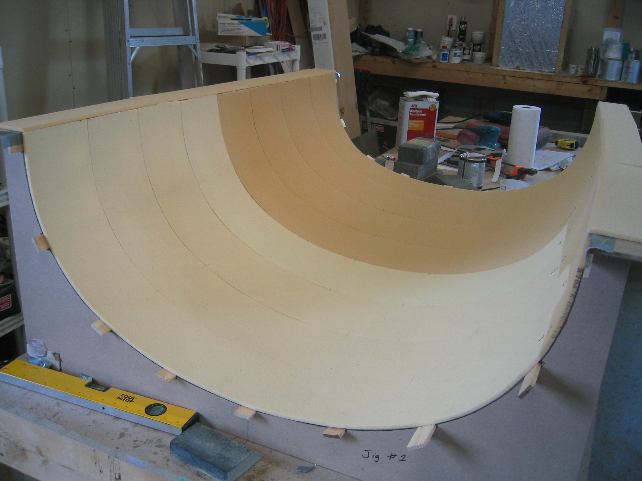
We start this chapter, like many others, by first building jigs. These jigs will form our “turtleback”, the portion behind the canopy bubble. The turtleback is available as a prefabricated part from two different suppliers. Much thought was given to the option of purchasing this part prefab. When we initially started this project we expected that we would purchase as many prefab parts as we could in order to save time. The reality, however, is that we have used as few prefabbed parts as possible. I believe there are two main reasons for this. First, we’ve been gaining experience and ability as we’ve been building. As we’ve come to the decision points for buying vs. building we’ve looked at the plans and have determined that there is, generally, little time savings to the available prefab components. The exceptions to this are the specialty metal parts that require machining.
So after the longest buy/build discussion we’ve had to date, the decision was to build the turtleback. Building the jigs for the turtleback, while not difficult, is somewhat tedious. Not one of the notches for the 1/4″ lattice to be installed, was accurately drawn on the template (despite the 1/4″ x 1 1/2″ spec being called out in the plans), thus each notch must be file fit to achieve a perfectly smooth contour when installing the lattice strips.
After the jigs were all cut, they were assembled on the worktable, and bondo was used to hold them in place. Then the lattice is installed in the notches, and 6″ wide strips of foam are slid into place. We used a helpful hint from Wayne Hicks to use drywall screws from the bottom of the lattice strips to help hold the foam tightly into the jig. 1.5″ wide strips of aluminum are taped into the jig at the seam of each 6″ strip of foam. After each strip is ‘file fit’ into the jig, it’s ready for glass.
Two plies of UNI are laid up on the inside surface of the turtleback, and peel ply is used at the cut line separating fore and aft portions of the turtleback, as well as at the TB1 bulkhead.
The TB1 bulkhead is then glassed, and a cut line is drawn on the inside surface of the turtleback. Small holes are drilled along the line to provide a means of transferring the line to the outside surface. A drip rail form is fashioned from 3/8″ PVC foam. We installed the TB1 bulkhead and glassed the drip rail.
A quick break from chapter 18 to install the center spar (thus finishing the last step of chapter 14) is taken at this point. On took a few days to do, and we were waiting for the canopy bubble, and some more epoxy anyway.
Next we took the turtleback out of the form, installed a metal reinforcement into the flange, and glassed the outside. We were very happy with how smooth the canopy turned out. Hats off to Wayne Hicks and his sheetrock screw method for holding the foam into the turtleback form. It worked really well!
With the outside of the turtleback glassed we started drawing out the cut lines for the windows. We didn’t like the way our cut lines were turning out. The plans diagram doesn’t give you all the dimensions, nor does it give you any angles. It looked like we would have to calculate some of the angles in order to figure out the missing dimensions. Before starting that exercise, we checked the FAQ quick. We found a great procedure in the FAQ using masking tape a few corner points to create the cutout areas rather quickly. After confirming that the windows we received from Todd’s canopies were bigger than the cutout area, we began cutting the window holes. We used a roll of electrical tape to radius the corners. Then we routed out the foam around the hole, trimmed the windows down to appropriate size, and slid them in.
We then apply acrylic backed tape to the windows around the frame edge, and pulled them back out. Then we sprayed a protective coating on the surface. This is done to protect the windows from damage during installation and the rest of the construction process. The windows are then floxed into place.
While we were waiting for things to dry with the windows, we floxed the canopy hinges onto the fuselage, and floxed the upper firewall in place. When the windows were cured, we proceeded to flox the turtleback onto the fuselage. When cured, we trim the flange on the turtleback to match the fuselage, and apply a bid tape.
Next we fit the canopy bubble to the turtleback and fuselage. We ordered our canopy bubble (with windows) from Todd’s Canopies. The canopy from Todd is just a little different shape (slightly more ‘raked’) than the one from Aircraft Plastics. We prefer the look of the one we got, but without knowing that the plans templates are based on the other one, we soon found ourselves scratching our head as to why the templates wouldn’t line up. A quick email to the list and to Todd confirmed that the shape was a little different, and that we just ignore the templates for the sake of fitting the bubble. It’s not a big deal, just good to know before hand for times sake.
After fitting the canopy bubble, we made the platform for stacking 2″ wide blocks of foam against the bubble to form the frame. Wayne Hicks has again found a better method for this at his site, and after carving the 18th block on the port side, we began to understand WHY he decided to do it differently. Carving each of the 2″ blocks to conform to the canopy is tedious. It took 24 blocks on each side of the canopy, and 1across the front. After completing the “stacking of the foam ritual”, you then still have to sand it to contour. This whole procedure took about 8 hours to complete.
With the canopy frame contoured, we were then able to glass the outside of it. The plane is REALLY starting to look like a plane now! After it cured, we then cut through the turtle back along the cut line to free the canopy. We then built the support frame around it, and lifted it free of the fuselage.
With the canopy upside down we shaped the inside foam, laid up reinforcing pads, and glassed the inside. We also took the time to finish the firewall reinforcement layups on the inside, and finish installing the firewall pieces.
Next we cut the fuselage top from the rest of the canopy, install the hinges, drip rails, and lips. There is also an instrument cover that is fabricated between the instrument panel and F28, which is held in place by fiberglass clips and sheet metal screws.
One of our earlier deviations from plans created a slight hiccup when we went to install the canopy lift strut. We purchased the strut called out for in the plans, but the plans have you attach it to the lower portion of the TB1 bulkhead (no problem), and the side of the passenger headrest. Being we are not using the plans headrests, but instead the rear headrests from an 3000GT, we don’t have the surface to mount it to. After a bit of playing around with a tape measure, and looking at the SPD website (plans hardware supplier), we determined that the SPD-5250-45 would suffice for our installation. This cross references a NAPA part number 819-5669. It is 18.5″ extended and 11.25″ compressed, with 45lbs. lifting force. We found one at the local Napa, and installed one hardpoint on the brace for the front seatback, and one on the TB1 bulkhead. This worked really well. Being the CZH canopy handle was no longer available we decided to find our own suitable replacement. A trip to the local Home Depot cabinet department yielded a handle which we liked very much.
While working on the canopy lift we also began work on the air vents. Two small NACA scoops are made into the side of the fuselage, and some ductwork is fabricated between the scoops and the vents which get installed in the instrument panel.
After many months working on other chapters we find ourselves revisiting this chapter for a little rework and to finish up some odds and ends.
First, the rework… We really didn’t like how the forward, starboard corner of the canopy frame and aft, starboard corner of the fuselage top turned out. This has to do with what most builders have accepted as ‘that darned hinge problem’. The issue stems from the fact the fuselage side is curved, and with a side opening canopy, the hinges will hang out a little at the forward and aft ends, more so at the forward end of a Cozy. When we built our canopy frame we decided it would look better if we kept enough frame over the hinge so as to hide it. The problem we found was that when viewing the plane nose on, we could notice the extra inch or so on the starboard side of the canopy frame. We also determined that it was going to take a LOT of micro to blend the fuselage side into the widened frame at that corner. As we prepare for the finishing steps it was time to face the music and decide how to correct the issue. We decided to compromise a bit. we sanded away the canopy frame so that we only had about 1/4″ or so of hinge exposed and determined that this would require only about 3/16-1/4″ of filler at the deepest part to blend in the fuselage side. After initial rework it looks pretty good. The true test will be if it looks good after final fill.
We also needed to finish installing the the NACA scoop to air vent ducts. We held off on installing them initially just to have easier access to the back of the instrument panel during the initial electrical work.
The last item is to install the canopy latches. We aren’t big fans of the plans latching system, but we’ve spent 3 years trying to devise a better one. So far we’ve only come up with ‘different’, not ‘better’. The plans hardware is not available prefab at the moment, so we have a couple weeks yet to come up with a better plan before we have CG Products send us the plans latching hardware.
Well…a couple of years has passed and we still couldn’t really devise a better latching system. Sadly, the plans latching hardware was still also near impossible to get. Fortunately, Jack Wilhelmson has improved the plans system in a fashion that appeals to us (removes the need for the leaky access door). His EZ-Rotary Latch (along with the appropriate plans hardware) can be found here. Once we started in on installing it we discovered that a recommended change to the location of the F28 bulkhead created a bit of a problem for us at this step.
The reinforcement points that are laid up in the canopy for mounting the latch brackets are positioned in reference to F28. Early on we followed the recommendation of the Cozy community (and Nat himself) and moved F28 .35″ aft of it’s original location. This shifted all of our reinforcement pieces aft by .35″ as well, and subsequently, our brackets are not centered on the reinforcements. Fortunately they are still all on the reinforcements, though I would caution anyone moving F28 aft as suggested to also move the pads aft by the same amount, or risk being on the ragged edge of them later. After about 10 hours of work, the latches are all mounted, and we’re ready to proceed with installing the rotary handle.