Start: 06/09/08
Finish: 09/27/10
Total Time: 122 Hours
This chapter is a milestone chapter for this project. The wing strakes and fuel tanks are the last of the large airframe components to be built. Completion of this chapter will signify completion of the structural components. We will have to cherish and savor this chapter a bit, as it will be the last of the large layups we will encounter.
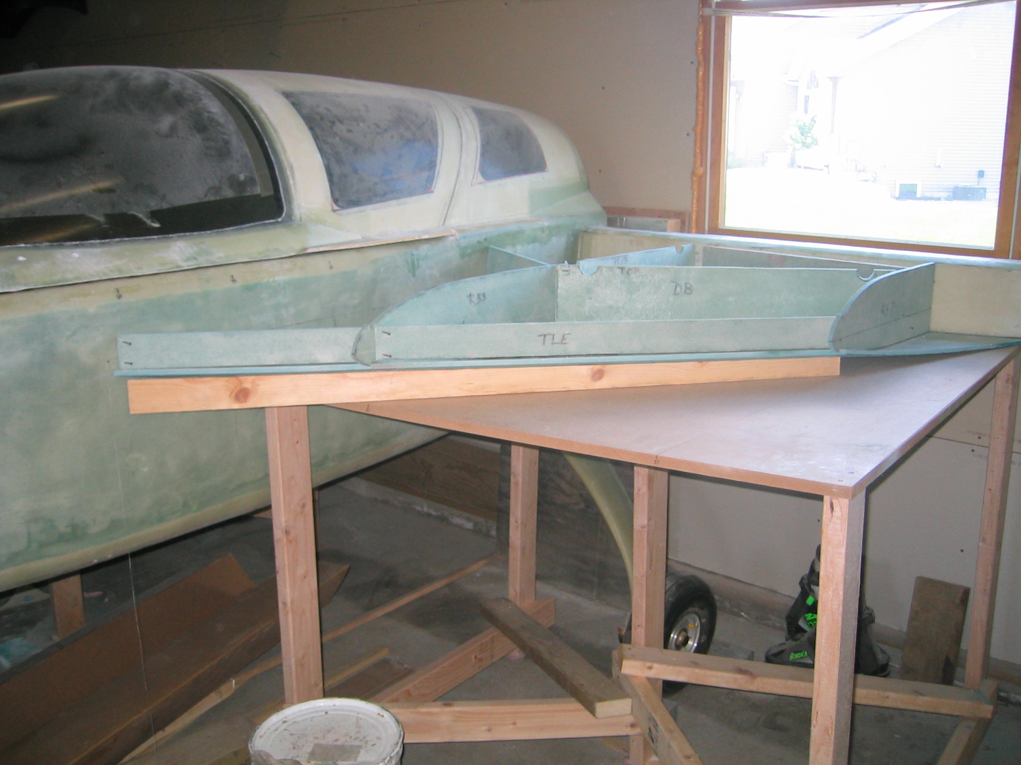
We started by ensuring that the fuselage is level fore to aft, and side to side. Then we built tables which fit snuggly to the underside of the wing spar, and as tightly as possible to the side of the fuselage. The tables are the jig platform from which we build our strakes.
Then we build the bulkheads and ribs which will give the strakes the correct shape, as well as divide them into fuel tank and baggage storage. Next the bottom skin core is glassed on the inside surface. Then we trial fit the bulkheads and ribs. We took another trick from Wayne Hicks for getting the ribs all at the right spot. We made 1/4″ templates of the wing at B.L. 67.5, and attached these to the outboard ends of the spar. The templates included the 14.7 W.L., which we also marked on the side of the fuselage. Using Wayne’s suggestion of dental floss, we strung it between the line on the fuselage, and the line on the wing templates. This gave us a reference for which to set the leading edge of the R33, and R57 ribs. We then used the plans method of the tapered board just to hold the leading edge 14.7 lines even with the dental floss. With everything set nicely, we floxed the pieces together, and proceeded to apply the bid tapes at all the joints. This is followed by a couple of coats of pure epoxy painted into the inside of the tank and baggage areas for sealing purposes.
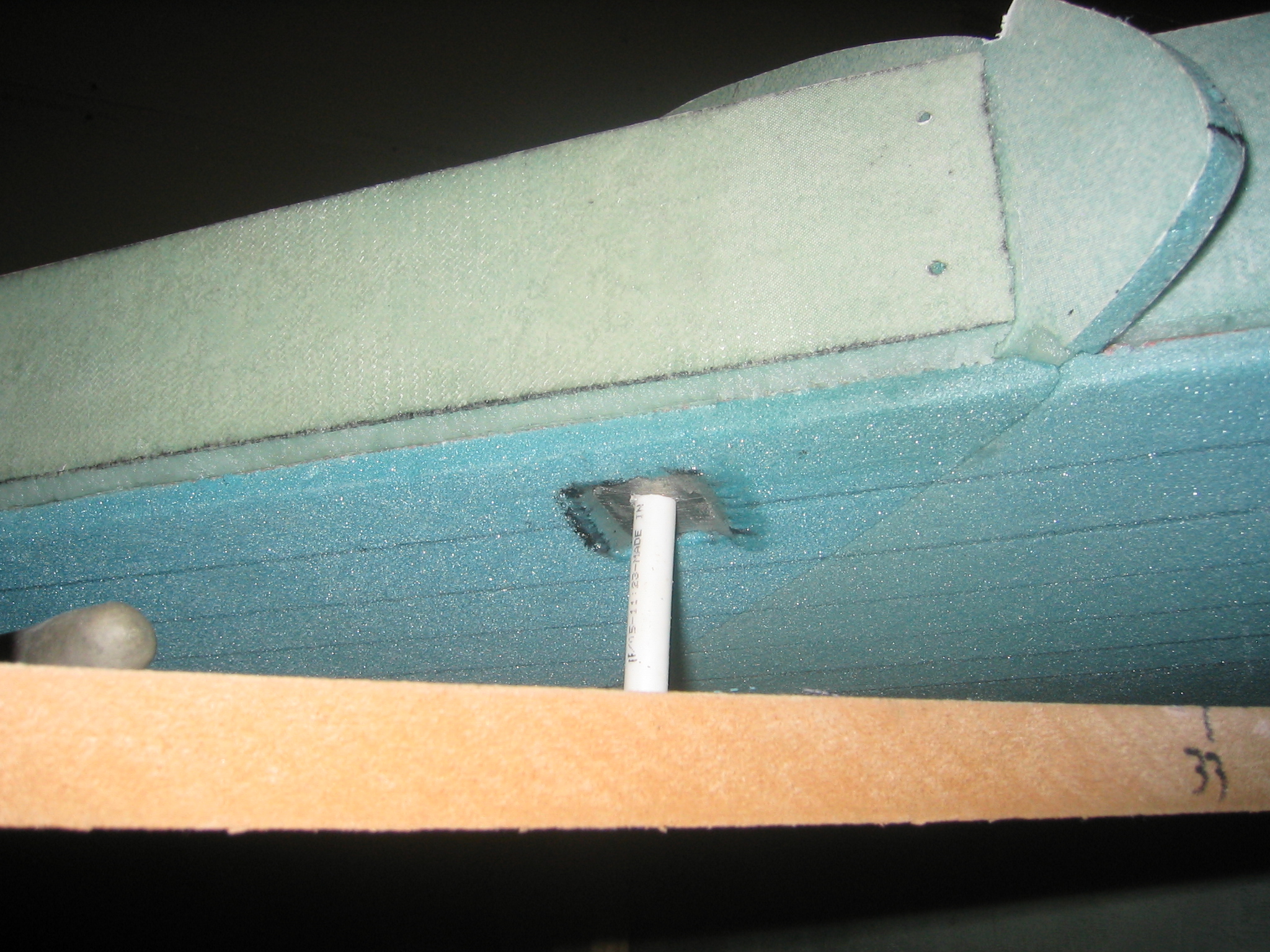
The fuel strainers at the outlets to the sump are typically just screen door type mesh. I found a tea ball in the housewares department of the local Wal-Mart that fit very nicely into this corner. The compartment behind the TTE bulkhead needs is filled with pour foam, which is really fun stuff. Mix up a few ounces of pour foam, and it expands to about 30 times it’s volume. After filling, it’s trimmed level to the top of the bulkheads. Metal reinforcement is also added in the bottom core at the forward end of the fuel tanks, for tapping a drain into. The fuel tank vent lines are also run through the bulkheads at this point.
Next we cut the top skin core and glassed the inside surface. Then the core is fitted to the strakes, and a frame is built on top to hold it in shape as it’s laid upside down on the workbench. Epoxy is then brushed onto the inside surfaces for sealing purposes.
Before closing the tanks up with the top skin, we had to decide on which method to use. The plans method involves simply floxing the top skin to the bulkheads. It is a simple process, and hundreds of flying canards have been built using this method. There is another method though, which endeavors to provide a bigger surface area (about double) for the flox to adhere to. The method known as T-Flanges or Capstrips involves building a 1″ wide bid flange on top of the bulkheads. This is the method we chose to use, even though it adds a few days of work, and may only provide a little extra assurance of a good seal.
The first step in the capstrip build process is to apply a layer of micro to the top of the bulkheads, then apply release tape to the top skin cores and weight down in place. After the micro cures the skin cores are removed, leaving a top bulkhead edge that is perfectly conformed to the curvature of the core. The micro is then sanded and release tape is reapplied to the skin core surface. A 2 ply 1 inch wide BID tape is then laid up along the line of the bulkheads. In order to help us determine the exact placement of those lines, we taped the top of the micro, as well as the skin core, and applied drops of automotive disc brake quiet to the top the bulkheads. Setting the skins back on top then transfers the dots. We probably went a bit overboard with the number of dots, but we then played connect-the-dots on the skin cores. Over the top of these lines we applied peel ply, and then the 2 ply BID tapes. The skin is then reapplied to the top of the strake bulkheads and weighted down for cure.
We struggled a little to determine how to drill and tap the holes for the fuel drains. We were unable to find a way to get a tap handle inside the tank, or under the strake (the jig table interfered). The plans don’t mention removing the jig table until after the top skin is floxed into position. We figured we could cut a section of the table away to allow us access to tap the hole, but feared compromising the integrity of the table. After pondering this a bit, we decided the table would be fine.
Just before floxing the top skin core in place, we took the opportunity to drill 3 small holes in the vent tubes at the back of the tank. This will allow the tank to vent when parked nose down. We then floxed the top skin in place, and weighted it down for cure.
After cure, we removed the jig tables and the support braces. Then we added a bit of foam along the fuselage side near the forward end of the baggage compartment. We discovered as we fit the top skin, that due to the bending at the leading edge, we ended up with a bit of a gap between the fuselage and the skin. We decided being it was just at the baggage area, we wouldn’t worry about it, and just cut a 1/2″ strip of foam to fill it.
We then fabricated the outside bulkheads, floxed them onto the ends, and flipped the plane upside down. To flip the plane, we rolled it outside, removed the main landing gear, and were lucky enough to have two of our neighbors, Brian and Tony, available to assist us. We set one corner of the spar down on a thick block of wing foam, and pivoted the plane on that point. The operation went very smoothly, and we didn’t damage anything other than the block of wing foam we used to protect the spar. Once we had the plane back into the garage, upside down, we faired the bottom strake core to the spar and rib tips, then glassed the outside surface of the OD bulkhead.
Next we glassed the bottom of the strakes, installed the fuel lines, fabricated the sumps, and glassed them in place.
Once again, we flipped the plane over, and proceeded to glass the top of the strakes. We then installed the Vance Atkinson fuel sight gauges, and made the foam leading edge blocks. We will wait with glassing them in place until after we receive our altimeter and conduct the leak test on the tanks.
We also needed to wait for our fuel level senders to arrive so I could drill and tap the hardpoints to the proper size. When they arrived we first needed to trim them to length. They came 12″ long, but we needed to trim them to 8″. The instructions say the probe should be at least 1/8″ off the floor of the tank, we cut ours a little under the 8″ mark to be certain it didn’t touch. Then we floxed the hardpoints into place and waited for them to cure.
At the suggestion of another builder, we built a home made manometer. To get the equivalent of 1500′ of air pressure we needed 14.325″ of differential water pressure, or just over 7″ from equilibrium. So we pressurized the tank, and then we wait, or so we thought…
We didn’t have to wait long to know if the tanks were air tight. As soon as we stopped the airflow from the compressor, we could hear a leak in the forward end of the port side baggage compartment. Upon further inspection we could see exactly where the leak was. We repaired the leaking area, and tested again the next day. At first, things seemed good. We didn’t hear any leaks right away. We stuck our heads and ears everywhere, and alas found another leak, this time in the starboard side fuel sump. It was very difficult to find at first until we squirted soapy water on it. It was right in the aft corner of the sump, where it meets the fuselage and strake. We again repaired the leak, using the plans procedure of drawing a vacuum in the tanks, painting epoxy in the leak area, letting it draw in, then removing the vacuum and applying more epoxy. Then we wait for the epoxy to cure, and then test again. This time with success. The manometer showed only a 1/2″ drop after 18 hours, the barometric pressure had increased from 30.10″ to 30.14″ though, which when one converts to water pressure is approximately a 1/2″. We’re happy to finally be able to glass the leading edges and close out the majority of this chapter. The only items to remain are the fuel caps (which are done after finishing), and the strake to wing fairing block (which is done at the time of finishing).
With the plane nearing completion, it was time to complete the last step of this chapter, installing the fuel caps. The plans tell you to wait until after you paint the plane, but we’re not going to paint it until after the phase 1 testing is complete. Seeing as how we don’t want to fill the tanks through the fuel lines, we have no choice but to install the caps now. It went pretty painless, though it took a little guts to take a 2 1/4″ hole saw to the finished top surface of the strakes. All is well though, and we can close out another chapter.