Start: 09/13/08
Finish: 05/08/11
Total Time: 501 Hours
This is the chapter every homebuilder dreams about…Installing the engine! We find ourselves ‘officially’ starting this chapter on 9/13/08. Truth be told, a lot of research and just plain SEARCHING has been going on the entire length of this project to date (almost 3 years and counting). We’ve looked at so many options for the power plant that most people who talk to us about the plane on a daily basis can hardly remember which option we’ve decided on.
We’ve considered an auto conversion using a Mazda Rotary, a vaporware turbine product known as Innodyn, and a 2-stroke diesel from Deltahawk. All were discounted when we asked ourselves one simple question: Are we willing to devote half or more of our build time to designing and installing engine components? We had to answer no.
In the end we followed the advice of an instrument that has yet to lead us astray…the plans. The plans call for the use of a Lycoming, horizontally opposed 4 cylinder. It can be either carbureted or fuel injected, either 320 or 360 cubic inches, and between 160 and 200hp.
We’ve chosen the Lycoming IO-360-C1C for our plane. It is fuel injected, 360 cubic inches, and produces 200hp. Choosing the prop is proving more difficult than first believed. We initially chose the AeroComposites, 2-blade, constant speed. But AeroComposites wouldn’t make a 2-blade for our plane, they insist it must be a 3-blade. The 3 blade design adds both cost and weight, along with sacrificing a little cruise speed. None of those things appeal to us.
So while we search for our motor we’ve started a few things that we can do. First, the engine cowling lips at the firewall. The cowlings (purchased from Featherlight), slide underneath lips fabricated at the firewall.
Before we can fit the cowlings to the turtleback we need to get the engine bolted in place. So one of the biggest landmarks in a homebuilders project was upon us. We had to buy the engine. We found an IO-360-C1C from Wentworth Aircraft in Minneapolis, MN. It has 2800SMOH (4700TTSN), so it will definitely need to be rebuilt before first flight. But we can address that while we’re working on the finishing.
Of course, in order to mount said powerplant to the plane we had either build or buy the engine mount. Not wanting to trust this crucial component to our own welding abilities, we purchased our mount from CG Products. CGP offers two variations of the Type 1 Dynofocal mount for the IO-360, a standard and HD mount (using thicker wall tubing). We chose the HD mount as the weight penalty was negligible. We centered and leveled the mount to the firewall, and drilled each of the 4 mounting holes. They are a very precise and snug fit.
The obvious next step was to hang the engine on the mount. With the engine now temporarily installed on the airframe we can fit the engine cowls. First a reinforcement rib is fit to the top cowling to prevent flex. Then the painstaking process of fitting the top cowling to the turtledeck and wing root. For the most part the fitment is pretty straight forward. The inside corners where the cosmetic pieces of firewall fit are a little trickier though. The plans would have you simply shave the cosmetic pieces to fit to the cowling. We’re going to have to make the cowling fit the cosmetic pieces however, as we placed our fuel sender probes in a location which we were expecting to be covered by fairing later on.
We chose to bolt the starboard wing on first, make all the necessary fitments and mounting lips, then bolt the other wing on and repeat.
With both wings bolted on, the garage is getting very cramped. It’s also very exciting to see it at this stage.
After making the port side cowling lips and ensuring proper fitment of the cowling at the forward, starboard and port edges, we find the trailing edge in much need of alignment. To fix the training edge misalignment we’ve decided to cut away most of the exhaust port area of the upper cowling, use pour foam as a plug for the area, and reshape it to our liking before re-glassing it for repair. Up to this point we’ve been pretty happy with the quality of the Featherlite Parts (landing gear legs, wheel covers, nose cone, etc), but the cowlings have proven a most disappointing fitment. Even prior to fitting them we noticed the trailing edges didn’t match up at all. We definitely wouldn’t recommend them. We’ve spent almost as much time reshaping/repairing these cowlings as it would have taken to simply make our own from scratch. Considering the cost of the cowlings themselves, and the insane cost to ship them (almost $500 to MN), they simply aren’t worth it. After completing the fitment, we cut out the oil access door and fitted it with a hinge.
In between steps to fit the cowling trailing edges, we completed the NACA scoop lips.
We then fitted all the nutplates to secure the cowlings, and began fabricating the baffles and heat shields. The baffle templates in the plans are for an O-360 (carbureted, parallel valve), which is also known as a ‘narrow deck’ engine. Our IO-360-C1C, is an angle valve, ‘wide deck’ engine. The baffles will be slightly different for out engine. In order to fit them as easy as possible, we first traced out the plans templates onto posterboard and cardboard. This allowed us to re-fit where needed easily.
With the posterboard baffling almost complete we needed to mount the exhaust, starter, and alternator in order to complete the last pieces. For the exhaust we chose the 4 pipe system from Custom Aircraft Parts. It exits at the stock exhaust locations on the cowling, and is made from 321 stainless steel. The plans recommends using a lightweight starter and alternator from B&C. We’ve chosen to use the PlanePower AL12-EI60 alternator. It is internally regulated with built in over-voltage protection. We’ve chosen the SkyTec HT lightweight starter. It is a high torque, wound field type. Both are much smaller and lighter than the stock components.
The next step was to transfer the posterboard templates of the baffles to the 6061 T6 aluminum.
One of the problems we’ve encountered is with the intake/oil sump. We selected the C1C variant due to reports that the C series intake sump placed the intake pipes in a position that did not interfere with the stock cowlings. The C1C poses other difficulties though. The first we encountered is the mounting orientation of the fuel servo. On the C1C the servo is rear facing, which on our pusher puts the opening all of about 1/2″ from the firewall. The sump is cast such that the servo could be mounted on the forward face…but it must be machined to accept it first. Once that was complete we could begin mounting the servo and setting the throttle and mixture controls to an orientation that would work for our configuration.
We also began mounting the oil cooler. The plans call for a 9 row oil cooler, though many have chosen 13 row coolers, and some have gone as large as 17 row. We chose to install a 17 row from the start. We mounted ours in the lower cowling, on the left side.
With the fuel servo now facing the rear of the plane, we needed to put a U bend between the air filter and the servo. A metal U bend is rather heavy, so to save weight, we used a metal bend as a form to produce a fiberglass one.
Unfortunately we couldn’t make the U bend tight enough to allow it to fit inside the cowling. The solution was going to have to be to attach the U bend directly to the sump, then mount the fuel servo on the the end of the U bend (facing into the NACA scoop). The air filter would only need a short little stub attached to the front of the fuel servo to clamp to.
While the fiberglass U bend seems strong as steel, we still decided to create fiberglass mounting brackets to help carry the weight of the servo, instead of letting it all hang on the U bend.
Next we needed to fabricate the fuel lines and mount the electric boost fuel pump.
One of last fitment steps we needed to complete (or so we thought) before removing the engine for rebuild was to fit all the sensors for the engine monitor. In our case this includes the 4 EGT and CHT probes, oil temp, oil presure, fuel pressure, fuel flow, and manifold pressure. Up to this point we hadn’t attached the intake pipes yet, which was probably a bit of a mistake. We didn’t think to install them yet as we didn’t think they were going to interfere with anything. One of the reasons we selected the C1C variant instead of the comparable A1A is that the intake tubes are farther forward in the cowling. In our engine research we noted that one builder had simply switched his A series sump for a C series in order to get the intake pipes to clear. We figured if we started with the C series we’d be fine. But there was a catch we didn’t discover until later. That builder was using the Aerocad cowlings which have a bit more room in the lower cowl. We didn’t discover this though until we bolted on the intake pipes in order to make sure we didn’t interfere with them when installing the EGT probes. So for all our efforts to avoid cutting up the cowlings yet again, we are forced to cut clearance holes for the intake tubes. We are then going to have make blisters around the tubes and contour them in to the lower strake fairings.
It was also time to get serious about selecting the propeller. We knew we wanted a constant speed propeller. We desired a 2 blade, though after talking with both AeroComposites and MT Propeller, it was becoming clear to us that most manufactures believed a 2 blade prop on a pusher created harmonic issues that caused problems for constant speed props. So we had 2 choices, both 3 blade, and both 51lbs. AeroComposites, which is a carbon fiber and kevlar construction, and MT-Propeller, which is wood and fiberglass construction. Lead time for the AeroComposites was 6-8months, where the MT was 6-8 weeks. The Aerocomposites was almost twice the price of the MT. The biggest drawback in our mind was the construction of the MT, we really didn’t want a wood and fiberglass prop. But then we got a tip, from a RV builder who suggested we look at WhirlWind Propellers. We gave them a call and were told they could build us a carbon fiber and kevlar, 3-blade (big surprise), 150 series prop for our plane. Total weight would be 37lbs, lead time was about 6-8 weeks, and the cost was about $3k LESS than the MT (making it about $10k less than the AeroComposites). It seemed too good to be true. We consulted with some other RV builders, who seem to be the majority of the WhirlWind customers. No one warned against them, and those flying them had nothing but good things to say. The only thing left to do was to finalize the colors of the plane so they could paint the prop to match. So we chose Starfire Pearl White as the main color, and Blue Ribbon Pearl as the trim color. Both are 3-stage paints, so we’ll have to get a professional involved when it comes time to spray the plane. With the colors selected, we submitted our prop order form and deposit. Our prop is currently scheduled to ship the beginning of August. The way things have been going, we’re just hopeful we’ll be ready for it by then.
Installing the throttle and mixture control cables turned out to be relatively easy. We took a suggestion from the Cozy list and bought our cables from Kartek Offroad. They were very reasonable (about $50 each), and are very high quality. We bought both throttle and mixture cables with 10-32 threaded rod ends, and utilized clevis rod ends at both ends. We will likely do the same for the prop control, but will wait until we have the governor to ensure proper fitment.
So with 298 hours into installing the engine, we then spent 2 hours removing it all in preparation for rebuild.
The engine we purchased had over 2800 hours on it since it’s last overhaul. Considering the recommended Time Between Overhaul (TBO) from Lycoming is 2000 hours, we knew when we bought it that we’d have to rebuild it before flying with it.
The plans suggest finding a mid-time engine that is proper working order so that one isn’t proving out an engine at the same time as the airframe. This is great advice, and had we found a mid time C1C when we needed to purchase we would have used one. Rebuilding will give us a better understanding of the engine though.
After removing the engine from the airframe when we were done with fitment, the first step was to disassemble the engine for cleaning and measurement.
We found a number of cracks in the crankcase after we got the sump and the cylinders removed. While we’re aware that crankcase cracks are not uncommon, we’re not familiar enough with these engines to determine which cracks can be repaired, and which, if any, are cause for discarding the case. We’ll leave that determination to the experts at the engine shop. We’re not particularly worried at this point though, as the business we purchased the engine from is reputable and guarantees the cases and crankshafts to make overhaul. Swapping out the case would only take a quick lunch hour errand.
As suspected, the extensive cracking in the crankcase was cause to reject it. It could not be repaired, so new crankcase halves were required. Wentworth Aircraft, where we purchased the engine, found suitable replacements, and delivered them to Bolduc Aviation (our chosen machine shop). The new case was inspected, found serviceable, and cleaned.
The crankshaft was also inspected, found to be in great condition, requiring only minor polishing (no undersizing of bearing surfaces would be required). The AD for the crankshaft gear was performed, and the rods were reconditioned and reassembled onto the crankshaft. The IO-360 rod bolts are tightened to length, not torqued to spec, and this is not a procedure we were familiar with, so we had Bolduc perform this step.
Our first step in reassembling the crankcase (after finishing the cleaning and inspection of all parts), was to get the one piece oil seal installed behind the prop flange. This sounds simple enough, but stretching it over the flange requires a lot of grease, both elbow and conventional.
The bearing surfaces are then lubricated and the crankcase mating surfaces are prepared for joining with anaerobic sealant and silk thread. The two piece front bearing on our IO-360 requires care be taken to mark the alignment of the bearing in the case, when installed into the dowels for it. With the crankcase assembled on the engine stand, we can now install the cylinder assemblies, and the accessory housing.
With the major assemblies together, we painted the engine. The color scheme we decided on for our engine is blue with black accents. It might be a bit much blue, but overall, we like it. With most of the engine assembly complete (just need a new fuel pump and an ignition system at this point), we’re about ready to bring it to Bolduc Aviation to be run in on a test cell.
After installing a new fuel pump, and procuring the ElectroAir ignition systems we transported the engine (including the GRT engine monitor) back to Bolduc for initial run in. Video from its run in can be seen here.
We had two minor issues to deal with after run in. First, the map sensor on the secondary ignition control unit (which was purchased used) was malfunctioning, causing that unit to lag the primary by 6-8 degrees. The engine still ran fine, but was about 50-70 rpm below the peak we were expecting. Second, my ‘guess’ at the midway point on the oil pressure regulator setting was about a turn too low, causing our peak warm oil pressure to be about 68-70psi or about 10psi low.
Aside from that, run in went very well. Peak CHTs never passed 370 deg, and peak oil temp was 172deg. After a couple hours of run in we drained the oil, ad cut open the filter. Both were very clean, and we deemed the engine fit for flight.
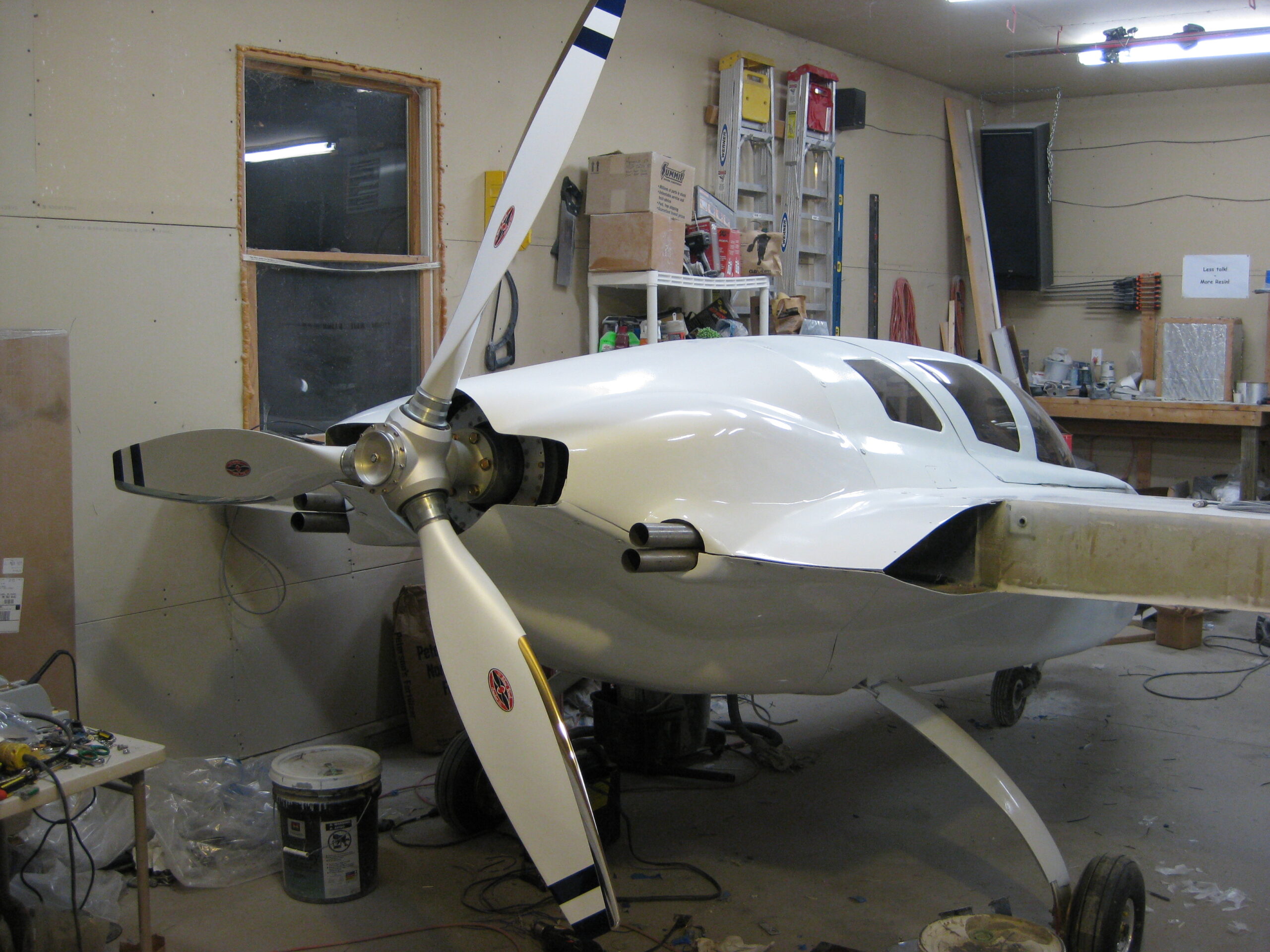
September 27th, 2010 one of the most beautiful propellers we’ve ever seen arrived at our house. The pictures we took before heading out the door for work just don’t do it justice, so we’ll take better ones soon. We were initially told that they could not spray a 3 stage paint on the propeller, so we selected a basic white and blue that were the same shade as the metallic pearl colors we intend to paint the plane. Much to our surprise Whirlwind had somehow managed to paint the prop with the pearl colors we chose, and it looks amazing! One issue we ran into after ordering the prop was that our original sales rep didn’t realize our engine wasn’t counterweighted. Fortunately the solution is simple. A harmonic dampener is added to the ring gear. The dampener is definitely larger than I had imagined, but shouldn’t pose any significant issue.
With the rebuild and engine run-in complete it was time to bolt the engine back onto the airframe. Once everything is reconnected we’ll be ready to do an first start up on the airframe.