Start: 09/14/08
Finish: 04/27/11
Total Time: 292 Hours
This chapter comprises of the final covers and fairings that are needed to close out the structure and provide some of the creature comforts.
We’ve started with the canard cover. We’ve deviated slightly from the plans build method, and constructed a fence around the canard in which to pour liquid expand-a-foam, or pour-foam. This allows a perfect conformity to the top of the canard, with zero gap around the edges.
After shaping, we determined that we’d prefer to have the canard cover removable to ease removal of other components. So we covered the foam with tape, and laid up 4 plies BID. One concern we had was that the cover would not be rigid enough. After cure we determined that it was indeed not rigid enough. To correct that we built a stiffening rib. Once floxed onto the bottom side of the canard cover, it was very rigid.
Next we made the thigh support ribs, which the front seat bottoms rest on. We built the front seat bottoms and the heat duct cover at this time too. Then floxed the thigh supports to the floor and glassed them in.
We then began fitting the armrests. Starting with the co-pilot side, we cut the armrest at the aft end to match the angle of he seatback, then proceeded to cut out the map pocket access, and stick access. Then repeated the process for the pilot side. The rear armrests went a bit quicker, but there is still a fair amount of trimming to get the fitment just right.
After they are trimmed to fit just right, they still require transition pieces to make the final fitment to the bulkheads. This process takes a fair amount of time (about 6 hours) to get the fitment nice and snug.
Next the rear seat bulkheads are made, along with the seat bottoms (which are curved on the front seat bulkheads before being moved to the rear), and the seat backs.
A cover for the rear heat duct is also built.
To install the rear seat bottom and backs we use pieces of hinge. This allow to seats to fold or (by pulling the hinge pins) be removed completely when additional storage capacity is needed.
With the seat structures and arm rests complete, we next fabricated the spar/turtle back cover. We’re not sure how we’re going to attach it yet, but we know we want this piece to be upholstered as well.
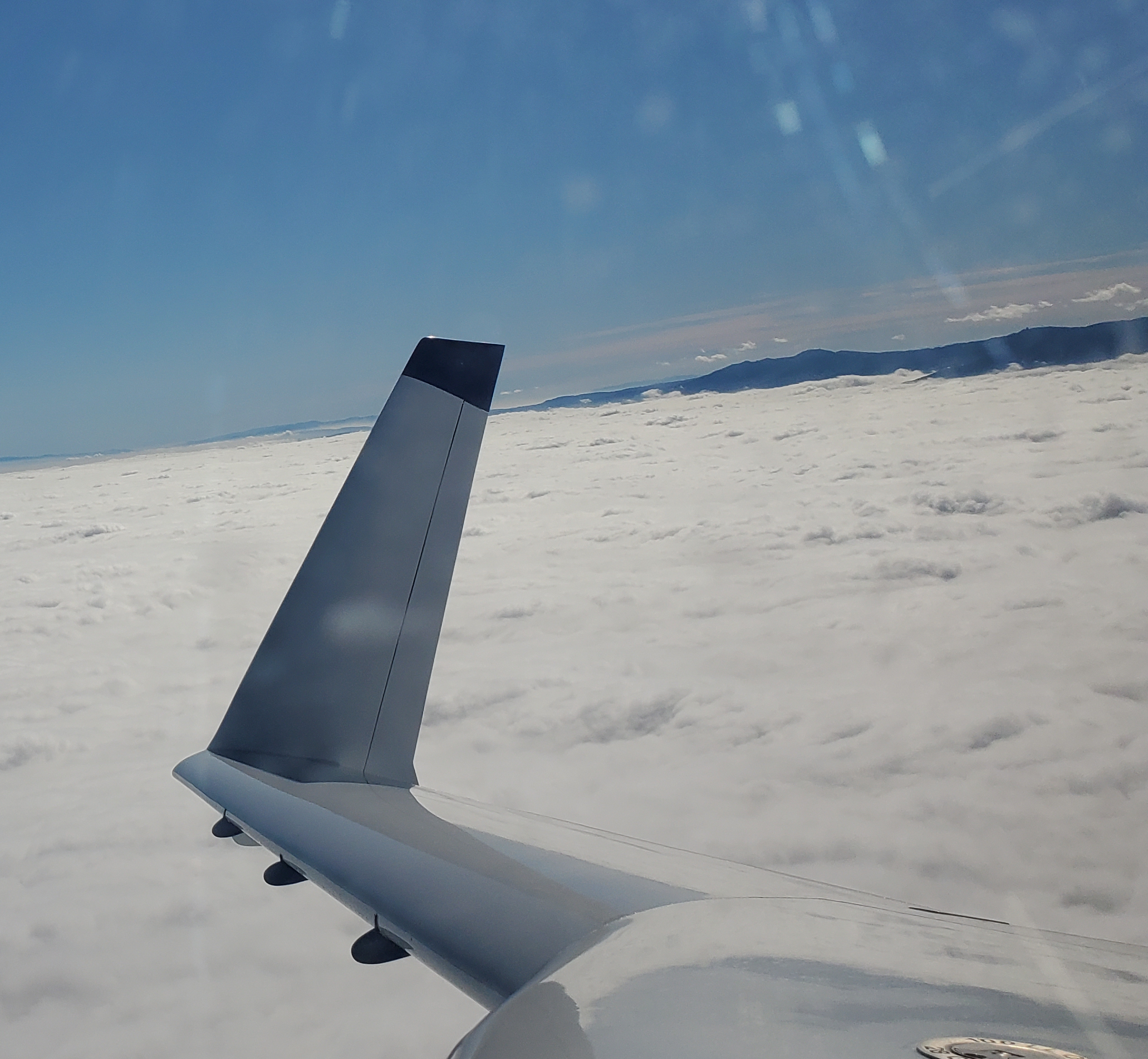
Next we attached the starboard wing so that we could fabricate the strake to wing fairing blocks and begin fitting the engine cowlings. After bolting on just one of the wings, another rush of adrenaline comes over you as you step back as realize there is fair chance this thing MIGHT just FLY!!! 🙂
The final interior cover is the center console. It houses the throttle quadrant, which we purchased from DJM Manufacturing. The RV builders love these quadrants, and when ours arrived we could see why. It’s perfect. Getting our center console perfect took a couple attempts though. Our first attempt wasn’t perfectly square and interfered with the fuel selector valve handle, so we scrapped it and tried again. The second one turned out much better. We had to make a groove and access hole in the side of it to allow for removal of the quadrant and working of the tension adjust. It will be covered with leather after finishing though.
Next we began shaping the lower strake to fuselage fairings.
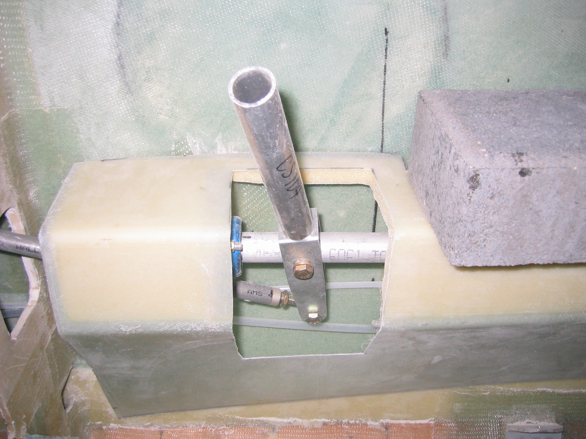
Before we could remove the wings we needed to seal the gap between the wings and main spar. This 1/2″ gap is created by the 1/4″ aluminum mounting plates as well as the 1/8″ protrusion from each bushing (wing and spar). The gap is seal with a strip of foam top and bottom, which is then sanded and glassed.
After completing what we refer to as the ‘electrical rough-in’ we could commence with the final install of the map pockets, armrests, heat duct cover, and center console. We also finished contouring and glassing the wing root fairing blocks.
The last step of this chapter is to make the upper strake fairings. These are constructed using pour foam. Once sanded to the elusive ‘pleasing shape’ they are glassed with a couple layers a bid, and the canopy split is cut back open. The rear canopy drip rail flange is then laid up. There is one final step in this chapter, the optional ice shields for the elevator counterweights. We will be installing these, but not until after first flight.