Start: 08/04/07
Finish: 11/02/07
Total Time: 187 Hours
Undoubtedly one of the most exciting chapters, we’ve finally gotten back on track and are tackling the wings. The first step is to make numerous jigs and templates, which will be used throughout the chapter. We then turn our attention to cutting the foam cores.
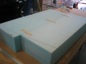
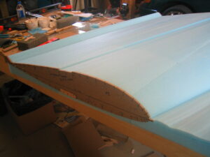
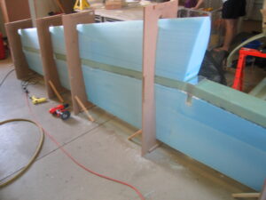
We’ll build the right wing first, no real reason, just that you have to start with one of them. Each wing is cut in 3 sections, each section, or planform, is comprised of between 3 and 4 blocks of foam 7″x14″x64″. After assembling the big ‘planform’ block from the smaller blocks, we attach the correct template to each end of the planform and using the hotwire saw, cut the airfoil shape out of the big foam block. This is much the same as the canard, but on a bigger scale.
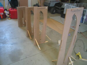
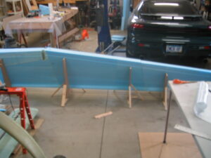
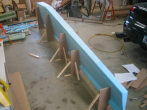
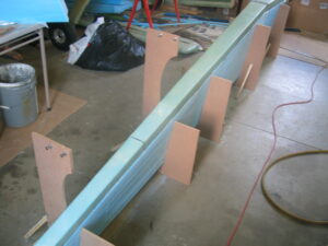
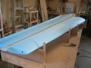
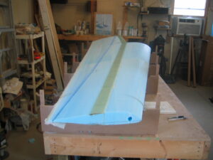
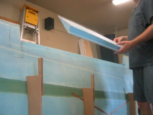
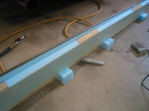
Once the airfoil shapes are cut, the leading edges are cut off at the spar cap trough and additional hotwire cuts are made for the aileron torque tubes, the electrical conduits, and the wing attach access cutouts. We found that the plans method of using popsicle sticks and 5 minute epoxy to hold the foam blocks together was a little unstable, and could cause too much foam damage if too much epoxy was used in an attempt to make a stronger ‘temporary’ bond. The sparing use of multi-temp hot glue used on the low setting, worked very well. it was strong enough to stay fixed during hotwire handling, yet could be broken apart with very little foam damage afterwards. Using very thin lines of glue instead of round blobs seemed to produced the best results. This also allowed for the stacking of blocks needed when the airfoil shape was larger than 7″ high (at the wing root). After splitting apart the various pieces that were temporarily affixed with hot glue, the hot glue is removed and wet micro used to adhere the pieces together permanently. Once each of the cores is permanently assembled, they are placed into jigs assembled on the floor.
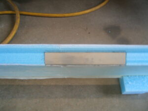
After assembly in the jigs with micro, depressions are cut out for access to the wing attach bolts, and the depressions are glassed. Aluminum hardpoints are then installed on the forward face of the wing root where the attach bolts go through. The shear web then laid up from the top to bottom spar cap trough, and the leading edge cores are microed into place. The leading edge half of the jigs is then placed back on the cores, and everything is checked for alignment before being allowed to cure.
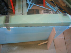
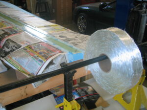
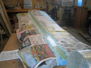
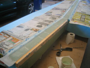
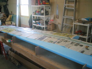
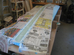
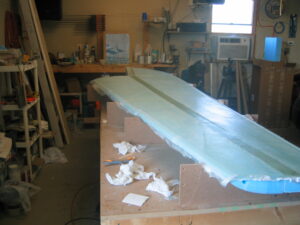
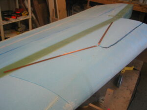
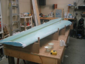
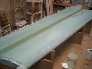
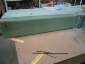
Once cured, the entire assembly is broken free from the floor and laid bottom side up on the workbench. We then glassed the bottom spar cap, and the bottom skin. The wing is then flipped, and we glass the top spar cap. Before glassing the top skin, we installed the first NAV antenna as well as the conduit for the rudder cable.
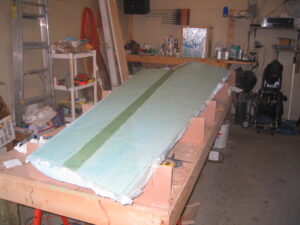
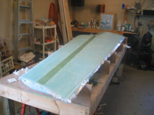
With the top skin cured we shaped the wing root ribs and glassed them, then proceeded to cut the aileron out from the trailing edge of the wing. A trailing edge spar is then laid up and reinforced where the aileron hinges are placed. The hinge brackets are then microed into the aileron along with the A10 control tube and a layer of BID applied over them.
We then notch the TE of the wing at the aileron cutout to accommodate the hinges. The plans have you fasten the hinges to the wing using screws through the top skin into nut plates fastened to the hinge. This leaves the screw heads raised on the top surface of the wing. We preferred to have a completely smooth top skin surface, accomplished using a device called a click-bond. It is essentially a stud with a thin, large diameter steel head on it, which you recess into the top skin and bond using flox and fiberglass. We then have studs to which we slide the hinges on and secure with stop nuts. The greatest challenge of hanging the ailerons was getting the hinge-to-aileron-to wing-trailing edge positioning correct. When trimming the wing trailing edge at the aileron cutout we trimmed only a tiny bit at a time, so as to keep the gap as small as possible that would allow free motion of the aileron.
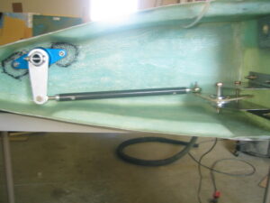
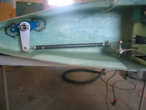
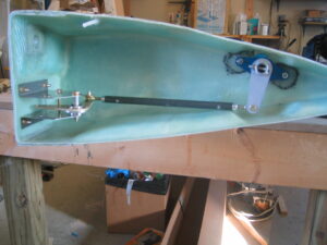
After the aileron is hung on the hinge, part of the control assembly is built and installed into the wing root. We found some issues with the chapter kits that Aircraft Spruce and Wicks sell when we got to this step. There was a change in the size of the rod ends used for these controls (MM4s instead of MM3s). That change has not been reflected in the materials kits provided by either supplier. Also, because these are chapter 16 (control system) parts being built and installed in chapter 19, there seemed to be some oversight by both suppliers concerning some of the required hardware. Most of the hardware used for the control system rigging is ordered with chapter 16, however the hardware to bolt the brackets in place is not included with neither chapter 16, nor 19 kits. I pointed this out to ACS, so hopefully they will add the hardware needed and change the MM3s to the appropriate MM4s.
With the right wing now complete, we start this whole procedure over…for the left wing.
The left wing is obviously just a mirror image of the right, so while we’re not taking additional photos of the left wing construction, work is progressing nicely. The left wing is going dramatically quicker than the right wing. This can be attributed to two forms of knowledge we gained during construction of the right wing. First, the process knowledge of exactly how each step impacts the next. This has allowed us to group certain tasks together in a fashion that allows the most efficient use of our work time for any given day. Second, the obvious technical knowledge gained through completing each task once already. There is far less head scratching and analysis of the plans this time around, as we know exactly what the wing should look like at each step.
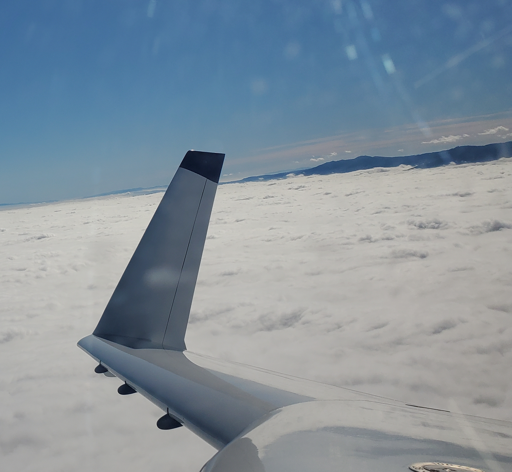
With the left wing mostly complete we ran into a slight problem. Somehow we did not have enough .75″ 6061 tubing left to make the aileron torque tube. It will only take a few days to get, but we’ll move ahead and start the winglets while we’re waiting. We’re also waiting for our spot facer tools to be sharpened, so we can’t drill the wing attach holes just yet either. We’ll move ahead and start the winglets while we’re waiting.
When our spot facer tools came back from sharpening, we spent the better part of a weekend drilling the holes for the wing attach bolts. Much like drilling the holes for the landing gear bolts, this is a slow, tedious procedure. You need to run the drill very slow, and alternate holes to avoid heat build up. You also need to clear the hole often to ensure the spot facer is making good contact with the surface. We found that drilling for a minute, then clearing the hole and rinsing the bit in cold water before moving to the next hole kept heat down and avoided dulling the spot facer. It took us about 11 hours total for this task, which included the time to jig one wing to the center section spar at a time. We didn’t really have an area large enough to jig both wings to the spar at once, so we leveled one wing on our build table, then using a folding table and some blocks, jigged the center spar level and mated to the wing. Being able to jig both wings to the spar would probably have saved an hour or two.
After the attach holes are drilled we installed the bushings and then installed the aileron controls in the wing root. The wings were now complete, and ready to attach the winglets.
